Microsemi LX3301A Manuel utilisateur

LX3301A/LX3302A
Auto Calibration User Guide
Preliminary
May 2018

Microsemi Proprietary and Confidential. LX3301A/LX3302A Auto Calibration User Guide Revision 1.0
Contents
1 Revision History ............................................................................................................................. 1
1.1 Revision 1.0 ........................................................................................................................................ 1
2 Software Installation and Validation .............................................................................................. 2
3 Data Preparation for IPCE .............................................................................................................. 7
3.1 LX3301A/LX3302A EEPROM Setting for Data Capture ....................................................................... 9
3.2 How to Capture Data Using IPCE Manually ........................................................................................ 9
3.3 Manual Data Capture Preparation Using LX3302A ............................................................................. 9
3.4 Data Validation ................................................................................................................................. 12
4 Calibration Using IPCE .................................................................................................................. 13
4.1 Loading Data/EEPROM into IPCE ...................................................................................................... 13
4.2 Example Data and EEPROM Parameters Loaded ............................................................................. 14
4.3 Calibration Condition Settings .......................................................................................................... 14
4.4 Auto Calibration ............................................................................................................................... 15
4.5 Auto Calibration of Phase ................................................................................................................. 16
4.6 Save Calibrated Result into EEPROM ................................................................................................ 17
5 Data Capture Using IPCE with Microsemi Bench Control System (BCS) ...................................... 19
5.1 Alternative Way to Take Data Using Dongle Programmer ............................................................... 19
5.2 Collect Measurements with Default Parameters ............................................................................. 19
5.3 Save EEPROM Data to File ................................................................................................................ 21

Microsemi Proprietary and Confidential. LX3301A/LX3302A Auto Calibration User Guide Revision 1.0 1
1 Revision History
The revision history describes the changes that were implemented in the document. The changes are
listed by revision, starting with the most current publication.
1.1 Revision 1.0
Revision 1.0 was published in May 2018. It was the first publication of this document.
Microsemi Proprietary and Confidential. LX3301A/LX3302A Auto Calibration User Guide Revision 1.0 2
2 Software Installation and Validation
The following section describes how to install and validate the software for the LX3301A/LX3302A
device.
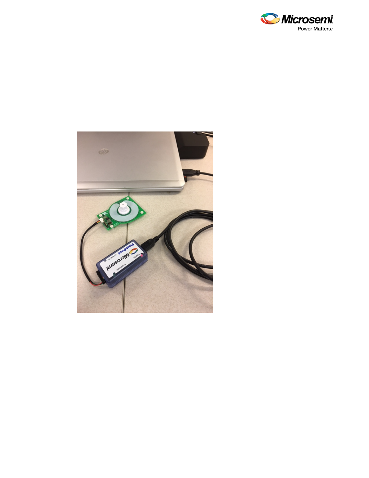
1. Connect the dongle to the computer.
2. Connect the sensor PCB to the dongle.
3. Place your target at a desired air gap.
The first three steps are shown in the following image.
Figure 1 • System Setup
4. Set up your bench system to take measurements.
5. Launch Integrated Programming and Calibration Environment (IPCE), as shown.

Microsemi Proprietary and Confidential. LX3301A/LX3302A Auto Calibration User Guide Revision 1.0 3
5. Launch Integrated Programming and Calibration Environment (IPCE), as shown.
Figure 2 • Launch IPCE
6. Verify that the port has opened, as shown.
Figure 3 • Verify Port Has Opened
Note: If it cannot recognize the dongle, then install the driver provided using device manager, then
unplug and replug the USB cable.
7. Read EEPROM from the chip (choose AOUT 11 for LX3301A or IO3 11 for LX3302A), as shown.

Microsemi Proprietary and Confidential. LX3301A/LX3302A Auto Calibration User Guide Revision 1.0 4
7. Read EEPROM from the chip (choose AOUT 11 for LX3301A or IO3 11 for LX3302A), as shown.
Figure 4 • Read EEPROM from Chip
If the result is the same as default parameters or previously programmed ones, then communication has
been done correctly.
If the result is as shown in the following three images, then communication has not been done correctly.
Note: Place the target with proper air gap distance if it won't read EEPROM correctly. Then, try to read
again. Adjust the target until it reads correctly.
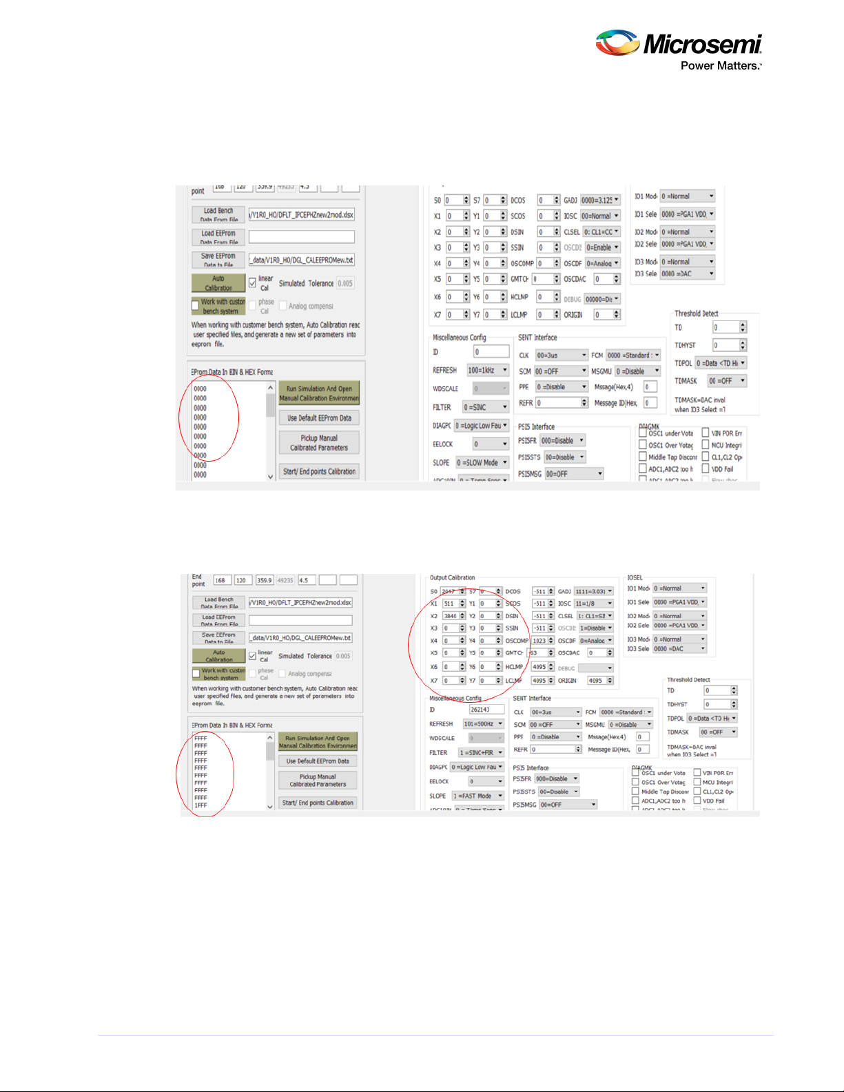
The following image shows an example of a communication error. The sensor board is not connected or
AOUT/IO3 is stuck high. All data is FFFF.
Figure 5 • Example Communication Error
The following image shows an example in which the IC detects fault or AOUT/IO3 is stuck at 0 V. The
Microsemi Proprietary and Confidential. LX3301A/LX3302A Auto Calibration User Guide Revision 1.0 5
The following image shows an example in which the IC detects fault or AOUT/IO3 is stuck at 0 V. The
sensor board is not connected or AOUT/IO3 is stuck high. All data is 0000.
Place the target in the proper position or fix AOUT/IO3 shorted GND.
Figure 6 • Example of IC Detects Fault or AOUT/IO3 Stuck at 0 V
The following image shows an example of IC unpowered (VIN). VIN is not connected. Data is garbled.
Figure 7 • Example of IC Unpowered
8. Use the default EEPROM data and write this default EEPROM data to the chip, as shown in the

Microsemi Proprietary and Confidential. LX3301A/LX3302A Auto Calibration User Guide Revision 1.0 6
8. Use the default EEPROM data and write this default EEPROM data to the chip, as shown in the
following image.
Figure 8 • Write Default EEPROM Data to Chip

Microsemi Proprietary and Confidential. LX3301A/LX3302A Auto Calibration User Guide Revision 1.0 7
3 Data Preparation for IPCE
The following section describes how to prepare the data for IPCE.
IPCE supports analog, PWN, and SENT data formats.
The following image shows an example of the analog data format for analog output. It provides the data
format template.
Figure 9 • Analog Data Format for Analog Output
The following image describes the data format for analog data.
Figure 10 • Data Format for Analog Data
SP position—Start point position on the data (target position). See the red arrow.
EP position—End point position on the data. See the blue arrow.
SP AOUT(V)—Start point AOUT voltage (for example, 0.5). See the green arrow.
EP AOUT(V)—End point AOUT voltage (for example, 4.5). See the purple arrow.
VIN—VIN voltage supplied to the sensor board.
A_Tolerance (V)—Allowable tolerance for auto calibration.
The following list describes data preparation using the Excel data template.
Position value must be arranged lowest to highest value (no negative slope).
SP_AOUT—Must be a low setting value.
EP_AOUT—Must be a high setting value.

Microsemi Proprietary and Confidential. LX3301A/LX3302A Auto Calibration User Guide Revision 1.0 8
EP_AOUT—Must be a high setting value.
Regardless of if the slope is negative or positive of the desired curve, SP must be a low value and
EP must be a high value.
SP position—Position of SP_AOUT value.
EP position—Position of EP_AOUT value.
Example—4.5 V (3 mm) –0.5 V (20 mm) (negative slope). SP_AOUT= 0.5 V, EP_AOUT= 4.5. SP
position= 20, EP position=3.
Figure 11 • Data Format for Analog
The following image shows the data format for PWM data.
Figure 12 • Data Format for PWM Data
SP position—Start point position on the data (target position). See the red arrow.
EP position—End point position on the data. See the blue arrow.
SP PWMDuty—Start point PWM duty (for example, 0.9). See the green arrow.
EP PWMDuty—End point PWM duty (for example, 0.1). See the purple arrow.
VIN—N/A.
PWM_Tolerance (duty)—Allowable tolerance for auto calibration.
Ce manuel convient aux modèles suivants
1
Table des matières


