MH Corbin Connect:ITS Manuel utilisateur

MH Corbin Connect:ITS
User Manual
Version 3.6
September 21, 2020
MH Corbin
6077 Frantz Rd Ste 203
Dublin OH 43017
800-380-1718
https://mhcorbin.com

This documentation is for your informational purposes only and is subject to change without notice by MH Corbin. This documentation may not be copied, transferred,
reproduced, disclosed, modified or duplicated, in whole or in part, without the prior written consent of MH Corbin. This documentation is confidential and constitutestrade
secrets proprietary to MH Corbin and may not be disclosed by you to any other person or entity or used for any other purpose.
If you are a licensed user of the software product(s) addressed in the documentation, you may print or otherwise make available a reasonable number of copies of the
documentation for internal use by you and your employees in connection with the use of the licensed software, provided that all MH Corbin copyright notices and legends are
affixed to each reproduced copy.
The right to print or otherwise make available copies of the documentation is limited to the period during which the applicable license for such software remains in full force and
effect. Should the license terminate for any reason, it is your responsibility to certify in writing to MH Corbin that all copies and partial copies of the documentation have been
returned to MH Corbin or destroyed.
TO THE EXTENT PERMITTED BY APPLICABLE LAW, MH Corbin PROVIDES THIS DOCUMENTATION “AS IS” WITHOUT WARRANTY OF ANY KIND, INCLUDING
WITHOUT LIMITATION, ANY IMPLIED WARRANTIES OF MERCHANTABILITY, FITNESS FOR A PARTICULAR PURPOSE, OR NONINFRINGEMENT. IN NO
EVENT WILL MH Corbin BE LIABLE TO YOU OR ANY THIRD PARTY FOR ANY LOSS OR DAMAGE, DIRECT OR INDIRECT, FROM THE USE OF THIS
DOCUMENTATION, INCLUDING WITHOUT LIMITATION, LOST PROFITS, LOST INVESTMENT, BUSINESS INTERRUPTION, GOODWILL, OR LOST DATA, EVEN
IF MH Corbin IS EXPRESSLY ADVISED IN ADVANCE OF THE POSSIBILITY OF SUCH LOSS OR DAMAGE.
The use of any software product(s) referenced in the documentation is governed by the applicable license agreement and such license agreement is not modified in any way by
the terms of this notice.
Copyright © 2020 MH Corbin. All rights reserved. All trademarks, trade names, service marks, and logos referenced herein belong to their respective
companies

Table of Contents
MH Corbin Connect:ITS User Manual ........................................................................ 1
Table of Contents...................................................................................................... 3
Installation ............................................................................................................... 7
Mounting.............................................................................................................. 7
Power Hook Up..................................................................................................... 7
Indicators and Connectors..................................................................................... 7
Connect:ITS 19 ............................................................................................................7
Front Panel LEDs ......................................................................................................7
Front Panel Connectors............................................................................................8
Rear Panel Connectors.............................................................................................9
Connect:ITS DIN ..........................................................................................................9
Front Panel...............................................................................................................9
Display Button Modes............................................................................................10
Front Panel LEDs ....................................................................................................10
Bottom Panel Connectors......................................................................................11
Antenna Connectors ..............................................................................................11
Exploded View of RS485 / GPIO Pinout .................................................................12
RS232 Connectors..................................................................................................13
USB Connectors......................................................................................................13
Power Connector ...................................................................................................13
Ethernet Ports........................................................................................................13
Display and Audio Connectors...............................................................................14
Setup / Modem Physical...................................................................................... 15
VX 21 Wireless Radio Install................................................................................. 16
Administration........................................................................................................ 17
Connecting to the Connect:ITS............................................................................. 17
Control Page ....................................................................................................... 18
Setup Page.......................................................................................................... 19
Location.....................................................................................................................19

Ping Remote Host .....................................................................................................19
SNMP and NTCIP Parameters ...................................................................................19
Configure V2I RSU Parameters Pre FW 1.0.42..........................................................20
Configure Lidar (Requires FW Restart) .....................................................................21
Configure Metiri and Telegraf (Requires FW Restart) ..............................................22
Metiri Application Snapshot Overview ..................................................................24
Watchdog Properties................................................................................................25
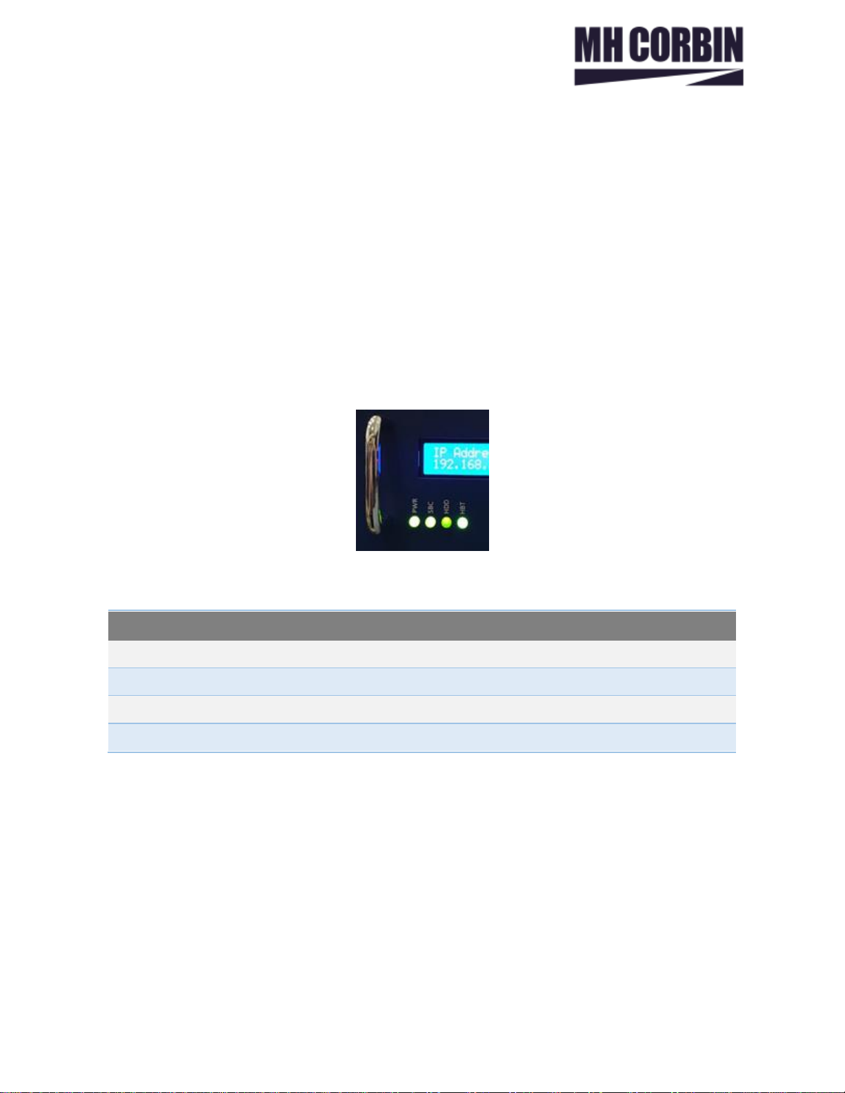
Disabling Items on Display Screen: IP Address .........................................................26
Disabling Backlight, and Heartbeat light...................................................................26
Backup and Restore ..................................................................................................26
Reboot / Reset Buttons.............................................................................................26
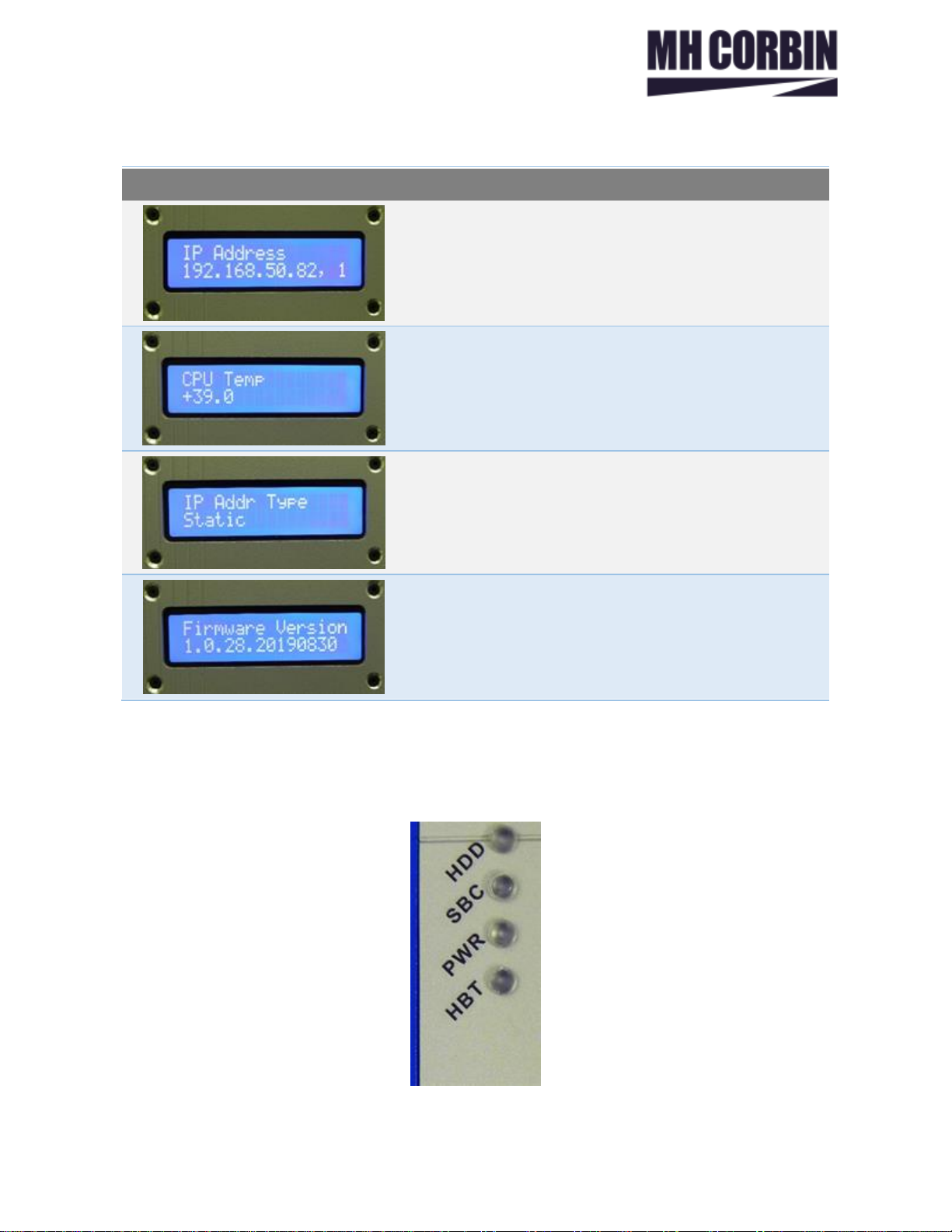
System Info ...............................................................................................................27
Setup/IP Page ..................................................................................................... 27
Single NIC Mode........................................................................................................27
Dual NICs and Bridged Mode....................................................................................27
Nameserver...............................................................................................................28
DHCP .........................................................................................................................28
MAC Address, Firmware Version, Refresh Date Stamp............................................28
Static IP .....................................................................................................................28
Setup/Logging Page............................................................................................. 29
Info Log .....................................................................................................................29
Debug Log .................................................................................................................29
Error Log....................................................................................................................30
Setup/Password Page.......................................................................................... 30
Setup/Firmware.................................................................................................. 31
Firmware Failure to Update and Resolution.............................................................32
Successful Firmware Update and 502 Error..............................................................32
Rolling Firmware Back...............................................................................................33
Setup/Units and Time.......................................................................................... 33
Setup/ITS Sensors Page ....................................................................................... 34
Sensors......................................................................................................................34
Adding New Sensors .................................................................................................35
Adding New Serial Sensor.........................................................................................36
Adding New Network Sensor....................................................................................36
Removing Configured Sensors..................................................................................37

Editing Configured Sensors.......................................................................................37
Setup/Modem Page ............................................................................................ 37
Step 1 - PPP peer port...............................................................................................38
Step 2 - Modem Provisioning....................................................................................38
Step 3 - PPP Chat Script.............................................................................................39
Step 4 - PPPo Adapters .............................................................................................39
Step 5 - Perform Manual PPP Connection ................................................................39
Step 6 - Show Addresses and Routing ......................................................................39
Step 7 - Change Default Route Step 7.......................................................................40
Frequently used Modem APN Strings.......................................................................40
Setup/Scripts Page .............................................................................................. 40
Creating Scripts.........................................................................................................41
Applications............................................................................................................ 43
Rest Api’s............................................................................................................ 43
Lidar....................................................................................................................... 44
Lidar Tab............................................................................................................. 44
Appendix A –Sensor Channels ................................................................................ 45
ISS ...................................................................................................................... 45
SX300 Statistical........................................................................................................45
Lufft.................................................................................................................... 45
WS100UMB...............................................................................................................45
WS200UMB...............................................................................................................45
WS300UMB...............................................................................................................46
WS400UMB...............................................................................................................46
WS500UMB...............................................................................................................46
WS600UMB...............................................................................................................47
VS2KUMB..................................................................................................................47
NIRS31UMB...............................................................................................................48
MARWIS StaRWIS......................................................................................................49
MH Corbin .......................................................................................................... 49
VX21..........................................................................................................................49
Vaisala................................................................................................................ 49
DSC111......................................................................................................................49
Wavetronix HD.................................................................................................... 50
HD125 .......................................................................................................................50

HD125 Periodic .........................................................................................................50
Appendix B –Database Schema............................................................................... 51
Change Log ............................................................................................................. 53

___________________________- 7 - ___________________________
Installation
Mounting
Connect:ITS comes configured for din-rail and shelf mounting. The Connect:ITS enclosure 3” D x 5” H x
6” W, and it weighs approximately 1.5lbs. It is recommended to install by placing the top mount point of
the Connect:ITS with the spring on the top of the rail first. While pressing the top of the Connect:ITS
down swing the bottom part of the mount inwards toward the rail.
Power Hook Up
Power is supplied through a 12VDC or 24VDC power supply, or from a 12VDC or 24VDC battery. Power is
provided via a 2-pin Phoenix connector on the bottom of the Connect:ITS.
Indicators and Connectors
Connect:ITS 19
Front Panel LEDs
Front
Panel LEDs
PWR
Lights green when the unit is receiving power from the backplane.
SBC
Lights green when the internal Computer has powered up.
HDD
Flashes green during disk activity
HBT
Flashes green when unit is operating normally.

___________________________- 8 - ___________________________
Front Panel Connectors
Front Panel
Connectors
RS485 #1, 2
Sensor Input connector for sensors that utilize the RS485 serial data
connections.
RS232 #1, 2
Connector for RS232 sensors.
USB #1, 2
Connector for USB sensors.
Cell
Antenna connector for internal cellular modem.
GPS
Antenna connector for internal cellular GPS.
VX
Antenna connector for 915Mhz internal radio.
Display Button
This button allows user to cycle through pertinent system information such as:
IP address, IP Mode, CPU Temp (C), Firmware Version

___________________________- 9 - ___________________________
Front Panel
Connectors
GPIO
10 General Purpose pins used for analog/digital inputs and outputs.
Rear Panel Connectors
Rear Panel
Connectors
Power Jack
12VDC Power Input (12VDC 2.5-amp) size 2.1mm X 5.5mm.
Fuse Holder
2.5-amp Slow Blow fuse.
Connect:ITS DIN
Front Panel
Connect:ITS
DIN Front Panel
LCD Screen
Displays unit information IP address, IP Mode, CPU Temp (C), Firmware Version
Display Button
This button allows user to cycle through pertinent system information such as:
IP address, IP Mode, CPU Temp (C), Firmware Version.
ON/OFF
This button turns the Connect:ITS DIN on and off

___________________________- 10 - ___________________________
Display Button Modes
First IP Address for Eth #1
CPU Temperature shown as Celsius.
Can be changed to Fahrenheit in Setup.
IP Address Type shown as Static. Can be changed to
DHCP in Setup.
Firmware Version
Front Panel LEDs
Table des matières
Manuels Système de sécurité populaires d'autres marques

EDM
EDM Solution 6+6 Wireless-AE Manuel utilisateur

Highway Safety Group
Highway Safety Group EA401 Manuel utilisateur

Siren
Siren LED GSM Manuel utilisateur

Detection Systems
Detection Systems 7090i Instructions de montage

Se-Kure Controls
Se-Kure Controls MicroMini SK-4841 Manuel utilisateur

Siemens
Siemens FDM273 Manuel utilisateur


