6
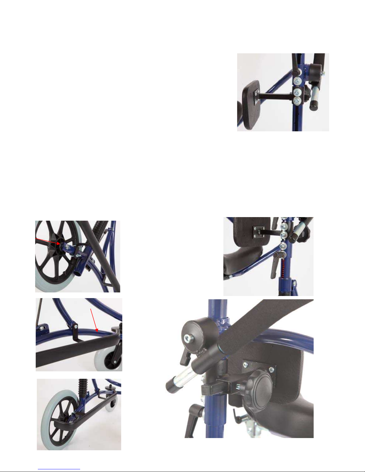
Rear stop:
The rear stop behind the seat can be
adjusted in lengthways direction. First
lift up the rear stop and tilt it back-
wards. This reveals an Allen screw
inside the U-profile When the Allen
screw is loosened, the rear stop can
be slid forwards or backwards in
the external tube. After adjustment,
retighten the Allen screw.
Handlebar:
The handlebar is mounted on each
side in a tube section located on a
cone. The cones are fixed in position
with Allen screws, and when these
are loosened, the handle bar can be
rotated around the cones. The hand-
lebar can also be slid forwards or
backwards in the two tube sections by
additionally slackening the two Allen
screws on the side of the handlebar.
Once the right positions have been
found, retighten the Allen screws.
Getting in and out:
MEYWALK® 2000 has an integral
lifting/lowering system, which facilita-
tes getting in and out for the user. We
recommend two helpers when getting
the user in and out. Press in the lock
fitting at the front of the MEYWALK®
2000 and raise the tilt bar.
On the MEYWALK® 2000 Small this
will lower the seat unit by about 13
cm (5”), on the MEYWALK® 2000
Medium by about 15 cm (6”), and on
the MEYWALK®2000 Large by about
25 cm (10”) . Then lift up and tilt back-
wards the rear stop and open the
trunk support. When the user is in
position on the seat, close the trunk
support and rear stop and raise the
seat unit by pressing the tilt bar
down until it locks with an audible
click. The integral gearing in the lif-
ting/ lowering system means that
downwards pressure need only be
about one third of the user’s weight.
Use of brakes:
The brakes are parking brakes which
function by directly blocking the rear
wheels with a fitting which presses
against the tire. To brake the walking
aid, pull the brake levers all
the way back until they come to a
definite stop. In this position the bra-
kes are self- locking. The brakes are
released by pushing the brake levers
forward again.
Adjustment af brakes:
First release the brakes by pushing
the brake levers forwards. Now slack-
en the two nuts which fi x the
brake mechanism to the bottom
frame. This will require a 10 mm
(13/32”) spanner. The whole brake
mechanism can now slide backwards
or forwards. Set it with a clearance of
3-5 mm (0,1”- 0,2”) between the bra-
ke fitting and the tire. Finally
retighten the two nuts and test the
brake action.