Medora SolarBee SB2500 Manuel utilisateur

Table of Contents
About Medora Corporation
Medora Corporation combines knowledge and experience from across the water quality spectrum
to help solve real-world problems. Whether in Lakes, Stormwater Retention Ponds, Raw Drinking-
Source Reservoirs, Water Treatment Plants, Potable Storage Tanks, or Wastewater Treatment
Processes, equipment continues to be at the forefront as the #1 world
leader for in-situ water body treatment.
www.medoraco.com | 866 - 437 - 8076 | [email protected]
1910_20170390
Table of Contents
SB2500 Owner's Manual
Safety 1
Operation 4
Features 5
Maintenance 16
Electrical 28
Technical Specifications 31
Troubleshooting 32
Parts Diagram 35
Dimension Drawing 36
Warranty 37
Customer Service 38
O&M_SB2500_20181115
www.medoraco.com | 866 - 437 - 8076 | [email protected]
1949_10036_20180820
Safety
Carefully read safety information when you see
any safety symbols:
Safety
Be sure you have read all installation, operation, maintenance and safety instructions
before you install, service or begin to operate this unit.
Accidents occur every year because of careless use of industrial equipment. You can avoid
hazards by following these safety instructions, and applying some ordinary common sense
when operating or servicing this unit.
Keep in mind that full operator attention and alertness are required when operating or
servicing this unit.
USE COMMON SENSE!! Most acccidents can be avoided by using common sense and
concentration on the job being done.
O&M_SB2500_20181115 - 1

www.medoraco.com | 866 - 437 - 8076 | [email protected]
1949_10036_20180820
Safety
Identify all possible hazards. Determine what
safeguards are needed and implement them.
Only you, the user, understand your product
and system characteristics fully. The ultimate
responsibility for safety is with you. Your
safety ultimately rests in your hands. Do
your part and you will enjoy safe, trouble free
operation for years to come. This instruction
manual is not intended to include a compre-
hensive listing of all details for all procedures
required for placement, operation and mainte-
nance. If you have a question about a proce-
dure or are uncertain about any detail, Do Not
Proceed. Please contact GridBee Customer
Service at 866-437-8076 to speak to a repre-
sentative.
IMPORTANT!!!
Follow all federal and state laws in regards
to safety regulations of working at heights,
conned spaces, rescue, etc. as required by
the U.S. Department of Labor, Occupational
Safety and Health Administration. Use
necessary PPE when placing and servicing
this unit.
ELECTRICAL HAZARD
WARNING: THIS EQUIPMENT CONTAINS HIGH
VOLTAGE! ELECTRICAL SHOCK CAN CAUSE
SERIOUS OR FATAL INJURY. ONLY QUALIFIED
PERSONNEL SHOULD ATTEMPT PLACEMENT,
OPERATION AND MAINTENANCE OF
ELECTRICAL EQUIPMENT. REMOVE ALL
SOURCES OF ELECTRICAL POWER BEFORE
PERFORMING ANY SERVICE WORK TO THE
MACHINE. USE PROPER LOCKOUT TAGOUT
(LOTO) PROCEDURES TO ENSURE A SAFE
WORK ENVIRONMENT.
Rotating Hazard
CAUTION: KEEP BODY APPENANDAGES OR
LOOSE CLOTHING AWAY FROM EQUIPMENT
WHILE OPERATING. ENSURE EQUIPMENT IS
OFF BEFORE ATTEMPTING SERVICE.
Crush Hazard
WARNING: DO NOT REMOVE ANY FLOAT
ASSEMBLY BOLTS OR PINS WHILE
EQUIPMENT IS FLOATING IN WATER.
EQUIPMENT MUST BE SECURELY
SUPPORTED BEFORE PERFORMING
SERVICE.
Safety
Laceration Hazard
CAUTION: EDGES MAY BE SHARP AND
CAUSE LACERATION IF PROPER CARE IS
NOT USED.
Entanglement Hazard
WARNING: ENSURE THAT PERSONNEL ARE
CLEAR OF THE ELECTRIC CORD AND CHAIN
TO AVOID ENTANGLEMENT.
Thin Ice Hazard
WARNING: ICE SURROUNDING MACHINE
MAY NOT SUPPORT WEIGHT, KEEP CLEAR OF
THIN ICE.
O&M_SB2500_20181115 - 2

www.medoraco.com | 866 - 437 - 8076 | [email protected]
1949_10036_20180820
Safety
Safety
Permit-Required
Conned Spaces
A conned space has limited openings for
entry or exit, is large enough for entering and
working, and is not designed for continuous
worker occupancy. Conned spaces include
underground reservoirs, ground storage tanks,
elevated tanks, silos, manholes, and pipelines.
Conned Space Tips
• Do not enter permit-required conned spaces
without being trained and without having a
permit to enter.
• Review, understand and follow employer’s
procedures before entering permit-required
conned spaces and know how and when
to exit.
• Before entry, identify any physical hazards.
• Before and during entry, test and monitor for
oxygen content, ammability, toxicity or
explosive hazards as necessary.
• Use fall protection, rescue, air monitoring,
ventilation, lighting and communication
equipment according to entry procedures.
• Maintain contact at all times with a trained
attendant either visually, via phone, or by
two-way radio. This monitoring system
enables the attendant and entry supervisor
to order you to evacuate and to alert
appropriately trained rescue personnel to
rescue entrants when needed.
Refer to 29 CFR 1910.146 for complete
regulations set by OSHA. Refer to your state's
regulations if your state established and
operates their own safety and health programs
approved by OSHA.
Protect Yourself
Medora Corporation insists that you
comply with all relative OSHA and local
regulations while installing and performing
any maintenance to the mixer circulation
equipment.
Key OSHA Compliance Standards that must
be followed (and not limited to) are:
• 1910.146 Permit-required conned spaces
• 1910.147 Lockout/Tagout
• 1926.500 Fall Protection
Fall Protection Tips
• Identify all potential tripping and fall hazards
before work starts.
• Look for fall hazards such as unprotected
oor openings/edges, shafts, open hatches,
stairwells, and roof openings/edges.
• Inspect fall protection and rescue equipment
for defects before use.
• Select, wear, and use fall protection and
rescue equipment appropriate for the task.
• Secure and stabilize all ladders before
climbing.
• Never stand on the top rung/step of a ladder.
• Use handrails when you go up or down stairs.
• Practice good housekeeping. Keep cords,
welding leads and air hoses out of walkways
or adjacent work areas.
Refer to 29 CFR 1926.500 for complete
regulations set by OSHA. Refer to your state's
regulations if your state established and
operates their own safety and health programs
approved by OSHA.
Lockout Tagout
When the On/Off switch is in the "ON" position,
the mixer may start up at any time if not
already operating. The mixer's On/Off switch
can be locked out by placing a pad lock thru
the door latch of the controller after the switch
has been turned to the "OFF" position. The
On/Off switch is to be used as the emergency
stop.
O&M_SB2500_20181115 - 3

www.medoraco.com | 866 - 437 - 8076 | [email protected]
Operation
The SolarBee is designed to circulate water
by bringing water from below and sending it
out across the top in a thin layer causing a
mixing effect. The laminar layer ows outward
radially, in diverging “stream lines” from the
distribution dish. As it does, vertical ow is
induced in between the water being drawn
below and the water above. At the level of the
ow intake, water is drawn from all corners of
the pond. As this lower layer of uid makes
its way inward with converging streamlines
to the SolarBee, the water is forced upward,
toward the surface, providing gentle mixing,
de-stratication, and surface renewal.
The SolarBee obtains all the energy it needs
from the sun. Its solar panels provide power
to the onboard battery which energizes the
drive system’s controls and motor. The new
Technology allows excess solar energy to be
stored during the day and used during the
night allowing the SolarBee to operate during
the night without being connected to the grid.
During operation, a visible ow can be
observed coming off the distributor dish
and spreading outward. The impeller of the
SolarBee is designed to operate at full speed
when there is sufcient sunlight and battery
charge. The rpms may drop down some
during the later night and early morning when
the battery uses up its charge after a longer
period of overcast days. In severe sunlight
limited conditions, the machine may slow
down or stop temporarily to protect the battery
from damage.
Operation
SB Series
SolarBee Flow Pattern
10199_20180625
Flow Coming Off Distribution Dish
O&M_SB2500_20181115 - 4

www.medoraco.com | 866 - 437 - 8076 | [email protected]
Features
SB2500
10258_20181113
Features
The SolarBee with technology includes new
features which enhance its performance
through more efcient and durable components,
improved operation monitoring capablilities, easy
component access, and a robust frame structure.
Solar / Electronics
Photovoltaic (PV) Modules -The PV modules
are often referred to as the solar panels. The
SolarBee uses 100% solar energy to provide day/
night operation. The PV modules collect solar
power to operate the machine with excess left
over to charge an onboard 12-volt, deep cycle
battery. The SolarBee has 3 80-watt PV modules
which individually connect to the digital controller.
A bird deterrent is located directly above the PV
modules to prevent bird fouling.
The PV modules have 3 angle settings that
are set at the factory based on solar energy
availability unique to the customer's geographic
location. The attest position is a 35 degree
angle for customers located where solar power
availability is greatest. The mid-range setting
position is a 45 degree angle for customers where
solar power availability is moderately available.
The steepest position is a 55 degree angle
intended for winter conditions to prevent snow
and ice buildup from lasting a long time period on
the PV modules (following winter conditions, the
PV modules should be returned to their original
position to maximize solar energy collection).
55 Degree
45 Degree
35 Degree
O&M_SB2500_20181115 - 5

www.medoraco.com | 866 - 437 - 8076 | [email protected]
Features
SB2500
10258_20181113
Features
For cable tethered anchoring, the north facing
panel may be ipped to face the south using a
special panel gate. A tethered machine is xed
and will not rotate, so the north facing panel will
receive the least sunlight, unless ipped using the
special gate. For mooring block anchoring, this is
not an option due to the machine rotating about
the mooring blocks.
Each PV module is xed to a gate that opens up
allowing quick access to the interior components
of the machine. Each gate opens by simply
removing a pin on the latch end.
Onboard Battery - The onboard battery is
located directly below the dish in a stainless
steel compartment. During operation, the
battery is submerged in the water to maintain a
stable-temperature environment that increases
its performance and life. The battery is double
walled to isolate its contents from the water it is
submerged in.
The onboard battery stores excess power from
the solar panels during the day and operates the
machine using the stored power during the night
and extremely overcast days.
PV Module Gate
Hinge End
Latch
End
Battery Compartment
Onboard Battery
O&M_SB2500_20181115 - 6

www.medoraco.com | 866 - 437 - 8076 | [email protected]
10258_20181113
Digital Controller - The digital controller is
located near the top center of the SolarBee.
The digital controller can be easily accessed by
opening the PV module gate directly above and in
front of it. The digital controller is constructed with
a NEMA 4X (IP 66) Enclosure.
All solar energy collection and motor operation are
managed by the digital controller. This component
has two primary functions: (1) To direct and divide
the power being collected by the PV modules
between the brushless motor and battery. (2) To
serve as the main control center that operates the
brushless motor.
There are 3 PV module connections located
on the front face of the digital controller. If the
onshore power accessory was purchased, a
connection will be located on the right side
face. The onshore connection is used only in
applications where onshore grid power is desired.
The left side face of the digital controller
contains the brushless motor connection, battery
connection, and On/Off switch. The On/Off switch
activates power to the motor. When the switch
is turned to the Off position, the motor will not
operate. The charging function of the controller
will continue to charge the battery even when the
switch is turned off.
Front Face Of Digital Controller
Left Side Face Of Digital Controller
Features
Features
SB2500
Digital Controller
PV Module
Gate Open
O&M_SB2500_20181115 - 7
www.medoraco.com | 866 - 437 - 8076 | [email protected]
10258_20181113
SCADA outputs offering machine operation
parameters reside within the digital controller.
Please contact Medora Corporation if you are
interested in receiving these parameters.
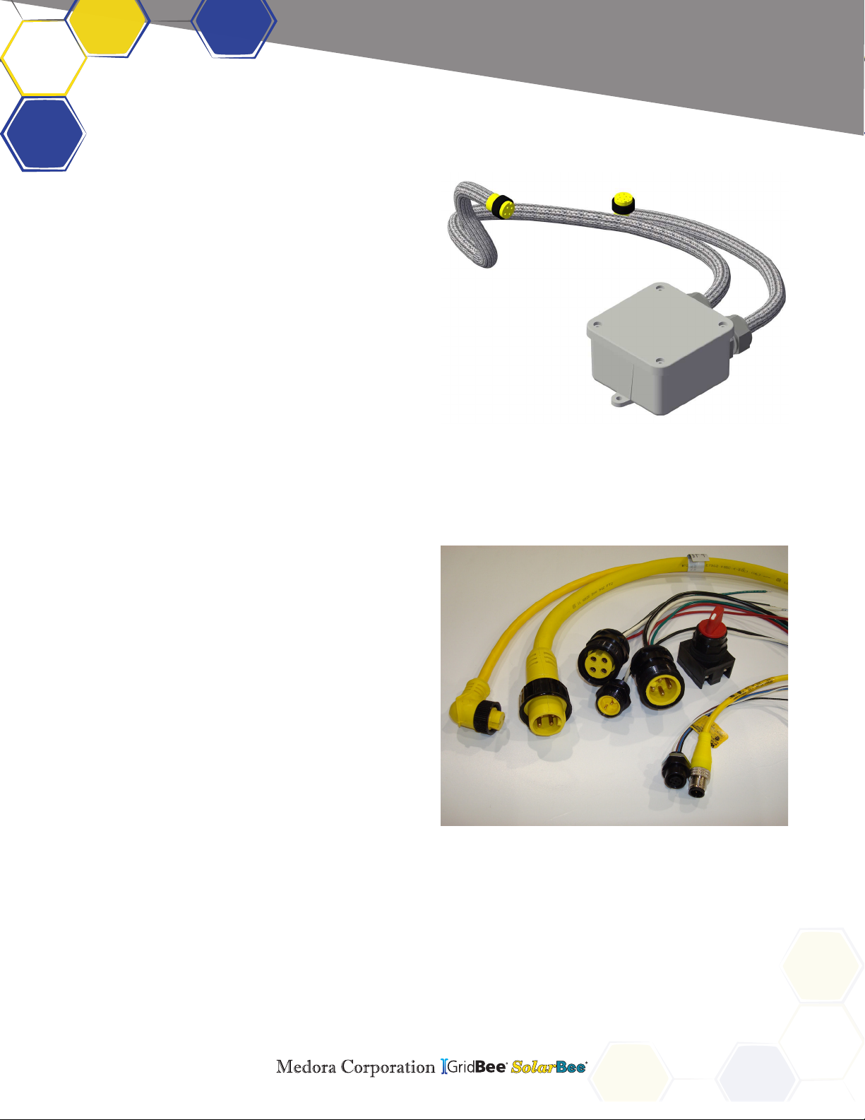
Motor Controller - The motor controller is located
near the motor just below the top plate of the
SolarBee. The motor controller is sealed in line
with the electrical cord that runs to the brushless
motor.
The motor controller on the SolarBee receives
power and signals from the main control center
located inside the external enlosure. These
signals are used to operate the brushless motor
at the commanded speed. The motor controller
also sends feedback signals back up to the main
control center.
Due to the high frequency of communication
between the motor controller and brushless motor,
the two components need to be located close
to one another. This is the primary reason for
having the motor controller located directly on the
SolarBee.
All electronic connections on the SolarBee
equipment should only be used for the inputs or
outputs that they are labeled and designed for. If
any of the leads going into the electronic controller
are disconnected, be sure when re-connecting to
place them in the proper position.
Wiring - All electric wiring includes corrosion-
resistant, industrial cords with molded, weather
and watertight connectors. The connectors
are indexed to prevent improper wiring. A
general electrical schematic can be found in the
Maintenance and Field Adjustment section.
Motor Control Cord
Durable Wiring And Connectors
Features
Features
SB2500
O&M_SB2500_20181115 - 8
Autres manuels Medora Onduleur


