MECHAPRO 3D-Step Manuel du propriétaire

www.mechapro.de • mechapro GmbH • Roermonder Str. 63 • D-52134 Herzogenrath page 1
Assembly Information
Stepper Motor Card >3D-Step<
Rev. 2.8 (last updated 5.1.2013)
Functional Desciption
The 3D-Step controller card enables the operation of 3 (optionally 4) stepper motors via
the parallel port of a standard PC. The phase current of the stepper motors can be raised
(boost) or reduced (sleep) by approx. 25% depending on the operating mode. In addition
four reference switches and one e-stop switch can be connected and looped right through
to the PC. The e-stop switch when activated will also cut off the L298 output driver ICs.
Several LEDs visualize the actual operating mode and the status of the reference switches.
Exclusion of Liability, EMC (electromagnetic compatibility)
Although all parts of the circuitry have been thoroughly tested mechapro does not give
any warranty or other assurance as to the operation or functionality of the circuitry or the
documentation. mechapro especially takes no responsibility for any damages caused by
reproduction, reverse engineering or initial operation of the here described circuits.
The stepping motor power amplifier “3D-Step” is an OEM product made for use in indus-
try, electronic trade and other EMC experienced sectors. According to EMVG §5, section 5
this product does not require CE qualification.
Cabling, used amplifiers, power supply and the surrounding environment are factors that
influence the EMC properties of a device. A device using one or more stepper motor po-
wer amplifiers must of course be evaluated according to corresponding directives, when
CE conformity must be documented. During development all possible means were used to
conform to EMC regulations.
Fitting with components
When fitting the board with components, make sure to follow the general rules:
• Start with the small components (resistors, diodes, capacitors, ...)
• Be careful to assemble with correct polarity (diodes, electrolytic caps, resistor arrays, ...)
• For the diodes D1 … D24 only fast switching diodes of the types BYV27, BYV28, BYW98
that can stand at least 100 V should be used.
• All ICs (except for LM2574N) should be set on sockets for safety reasons. For the L298s
single line sockets (high 8-8.5 mm) can be used. Cut the sockets to the length required.
Make sure both socket rows are aligned in the same direction. Do not use precision sockets
with turned contacts.
• The heat sink (type V6717Z, or SK96/84 -> only 84 mm wide) has fitted threads. Before
plugging in the L298’s, screw the heat sink with the plastic spacers onto the board, then
align the ICs and screw them into the heat sink.
• Before final mounting of the L298’s it is recommended to apply a thin(!) layer of heat
conducting paste to the ICs, to achive good heat dissipation. No isolating material required
between heatsink and L298.

page 2 www.mechapro.de • mechapro GmbH • Roermonder Str. 63 • D-52134 Herzogenrath
• In use, depending on the environment, it may be necessary to use an additional fan for
cooling. If the casing is already well ventilated, it may not be necessary to use an additional
fan, if the board is mounted in the air-stream.
Initial Operation
Before the initial operation do a visual test of all the soldering joints and the components.
Make sure all ICs have been inserted in the proper orientation. Check for short cuts on the
parallel port connector (LPT) as well as the soldering joints on the L298s. All potentiometers
and jumpers should be set to the default positions according to the layout diagram. Leave
the stepper motors and the PC disconnected.
At first open JP1 and apply power the board. The right pin on JP1 (in direction of screw ter-
minals) should carry 5V DC with respect to ground. If the voltage is OK (+/-5%), close JP1.
For the following tests some of the jumpers have to be changed. Normaly this should be
done when the power is switched off only. But if the PC is disconnected and the motors
are disconnected, the jumpers may be changed without switching the logic voltage off.
After power on all green LEDs and the red NOTAUS (e-Stop) LED should be lit. When both
jumpers JP4 (SLEEP) are turned by 90 degree, the green SLEEP LED turns off and the yellow
NORMAL LED is lit. After changing the jumper JP3 (BOOST), the NORMAL LED turns off
and the red BOOST LED is lit instead. By changing JP2 the DISABLE LED is turned off. Now
set the jumpers JP2 and JP3 back to their default positions, while keeping JP4 turned by
90°.
Now you can adjust the reference voltages for the current regulators with the trimmers
R28, R29 and R30. If the NORMAL LED is not lit, change both SLEEP jumpers JP4 to the
“on low” position (see jumper desciption for details), JP3 (BOOST) to “disable”, disconnect
the PC. The reference voltages are measured with respect to ground at R3, R8 and R13 on
the side facing towards the trimmers. The set/measured voltage V(ref) has the following
interrelation with the motor current:
V(ref)=I(motor)*R(sense)*sqrt2 (sqrt2=1.41)
Therefor V(ref) gives the set value for the current regulator. R(sense) is the respective sen-
sing resistor on the board (0.47 ohms in the standard assembly). For 1A motor current you
have to set V(ref) to 0.665V for example. If the adjustments are done, set back the jumpers
to the default settings as before.
The chopper frequency can be measured on the sync-pins (pin no. 1) of the L297, however,
be sure not to short cut with pin no. 2!
Now you are ready to test the card with the motors. To do this you’ll have to connect the
card to the LPT- port of the PC. Than boot the PC. Always make sure to boot the PC first
and start the software. Only then apply the voltage to power the board and supply the
stepper motors. During the boot process of the computer some signal levels might change
leading to unexpected reactions of the motors.
For the test itself we recommend the free demo version of WinPCNC but you may also wri-
te a small program yourself. For the beginning you should start with moderate low supply-
voltage of 12 - 15 V for the steppers. This may be taken from a laboratory power supply
with current limitation if available.

www.mechapro.de • mechapro GmbH • Roermonder Str. 63 • D-52134 Herzogenrath page 3
Meaning of different Jumper Positions
JP1: Connection from internal power converter (5V output) to logic supply of the
board. Open only for testing during inital startup.
JP2: „used“ (default) - an e-stop switch is connected. „not used“ - monitoring of e-
stop is deactivated (only for test purposes recommended)
JP3: „active“ - the BOOST function will raise the current to 120% of the target cur-
rent during brake and acceleration (requires support by software being used).
„disable“ (default) - BOOST-function is disabled.
IMPORTANT: Use the BOOST function only when all axes are set to phase cur-
rents below 1.5A to avoid overloading the drivers!
JP4: „on high“ (default) or „on low“. Determines whether or not the reduction of
the current (approx. 25% of the target current) is activated on LOW level or
HIGH level. The polarity is normaly set within the CNC software (WinPCNC,
Mach3,...).
MODE: upper jumper: „phase chopping“ (slow decay, default) or „enable chopping“
(fast decay). Will influence the way of how the current is controlled. Generally
the default position will lead to the better results. For additional information see
the application notes of www.st.com or in the stepper motor blog (german):
www.schrittmotor-blog.de.
lower jumper: „half step“ (default) or „full step“ operation. In fullstep mode,
stepper motors are more sensitive to resonate, so half step is allways recom-
mended.
ATTENTION: never leave off one jumper completely.
Meaning of LEDs
ENDX: Signals that the limit/reference switch of the X axis is activated. When “normaly
open” contacts are used instead of “normaly closed” contacts, the LED is on all
the time except when the switch is activated.
ENDY, ENDZ, ENDC: Same than for X axis. If no 4th axis is used, ENDC can be used as a
general purpose input.
SLEEP: Signals that the current reduction mode is active. This feature is activated by the
PC with the SLEEP input line (pin 17).
NORMAL: The motors are powered with the adjusted nominal current
BOOST: The current boost is active (input to pin 16), the motorcurrent is raised to aprox.
120%. If your software does not support this feature, the BOOST input has to
be disabled (default jumper position). The BOOST function must not be active
permanently, because it will overheat the power stages and therfore may de-
stroy them.
NOTAUS: The NOTAUS (=e-Stop) LED signals that the e-Stop switch is activated. The
e-Stop input disables the power stages and is signaled to the PC. The e-Stop
switch has to be a “normaly closed” contact.

page 4 www.mechapro.de • mechapro GmbH • Roermonder Str. 63 • D-52134 Herzogenrath
External Connections
• For connection to the PC use a 26pin ribbon cable. The lead no. 26 can be omitted and
be cut shorter. Be careful, however, not to short cut with other components since this lead
carries 5 V to eventually supply the optional optocoupler board or other add-ons. For con-
nection outside of the housing a 1:1 shielded cable should be used.
• When using older DOS programms some leads have to be crossed. Please refere to the
standard pinout and the documentation of your software. You may also ask for help in our
forum. For WinPCNC, PCNC, Mach3 and pcdreh for windows no changes to the wiring are
required.
• The limit-/or reference switches and the e-STOP switch have to be connected to the
SWITCHES port as break contacts to ground. Easiest way is to use a 9 pin ribbon cable to
9pin D-Sub and from there use a standard screened 9pin d-sub cable for connection to the
machine. The board will not work without an e-Stop switch connected. For testing purpo-
ses the monitoring of the e-Stop switch can be disabled with the NOTAUS jumper.
• The connector for the C axis can be used to connect an add-on board for a fourth axis.
The Tiny-Step or HP-Step board can be connected directly to this port. Instead of a 4th axis
it is of course possible to use a second power stage on one of the existing axes if two mo-
tors have to be used in a gantry configuration. In this case the signals for the C axis coming
from the PC have to be disconnected and wired to the respecting other axis (X, Y or Z).
• The stepper motors are connected to the terminal blocks. Each pair of connectors (X1X2,
Y1Y2, Z1….) is reserved for the two leads belonging to one coil of the steppers. To change
the direction of rotation, simply change the polarity of the leads on one coil on the termi-
nal block. When using unipolar stepper motors with 5 or 6 leads, the center taps of the
coils won’t be used but must be perfectly insulated. Don’t connect them to + or ground.
Bipolar stepper motors that have 8 wires allowing for connection of two coils in series or
parallel. The serial connection will always
work, the latter may offer a higher rotati-
onal speed for which you have to pay the
price of a higher current leading to a lower
torque when the phase current exceeds
2 amps. Using this arrangement the coil
resistance is cut to half and should not fall
below 0.8 Ohms. Once you are above that
you may try both options.
Motor wiring
Connection of limit and reference switches

www.mechapro.de • mechapro GmbH • Roermonder Str. 63 • D-52134 Herzogenrath page 5
Additional Hints
• In case the phase current of a stepper motor will significantly be lower than 1 amp it may
be useful to match the resistors R1, R2, R6, R7, R11 and R12. We recommend 1 Ohm. Of
course this new value has to be considered when doing the adjustment for the reference
voltage Vref.
• If not all the axes are needed, the respective power ICs (L297/L298) can be omitted. The
L297 (IC1) on the X axis must be installed in any circumstances, because this IC generates
the clock for all other current regulators!
Problems & Solutions
There are problems with noise on the steppers:
• Instead of phase-chopping you may try inhibit-chopping
• Do a check on the reference voltage Vref
The phase current won’t reach its target value or the motor has not enough torque when
running:
• Do a check on the reference voltage Vref
• Change the position of the SLEEP jumpers (turn both by 90 degree)
NOTE: The phase current control is based on the max. value. The resulting average value
will be a little lower.
The motors don‘t have any holding torque:
• Check eStop switch or change JP2 (for testing only)
• Check power supply
The stepper motor driving the z-axis won’t turn or only turns in one direction:
• The resistor array RN2 has been inserted in the wrong orientation.
Hints for Troubleshooting
In case the circuitry doesn’t work from the start up or any defect has occurred please find
out what the defect is and have it fixed. Then before connecting the stepper motors repeat
the start up procedure as described above.
The following hints may help you to find a defect:
• Can you measure the correct voltages (between 0 and 1V) on the test points for Vref
even when changing the level for SLEEP or BOOST ?
• Is the ENABLE-pin on the L297s (Pin 10) on HIGH level?
• Often the corresponding L297 will also be destroyed if the L298 is blown. In case of dou-
bt you may as well replace both of them.
Please read the documentation carefully at first and check the circuitry. You may also visit
the mechapro homepage at www.mechapro.de in order to look for hints and bug fixes. If
these hints and the additional help at our forum on www.mechapro.de don’t answer all
your questions, contact us for further help by email. Please provide a detailed description of
the problem and your configuration. (type of power supply, used software a.s.o.) -> E-Mail:

page 6 www.mechapro.de • mechapro GmbH • Roermonder Str. 63 • D-52134 Herzogenrath

www.mechapro.de • mechapro GmbH • Roermonder Str. 63 • D-52134 Herzogenrath page 7
page 8 www.mechapro.de • mechapro GmbH • Roermonder Str. 63 • D-52134 Herzogenrath
Technical data
Power Supply (logic): 5 Volt +/- 5%
Rated current (logic, without LEDs): typically 200 milliamps
Rated voltage (power stage): 10 … 45 V
Rated current (power stage): depending on rated voltage and type of stepper
motors being used. Maximum over all current
6 amps.
Control: Pulse/direction, CMOS compatible
Step resolution: Half-/Full-step
Number of axes: 3 independent axes control allowing for
2 amps phase current per motor
Circuitry: Not short-circuit proof
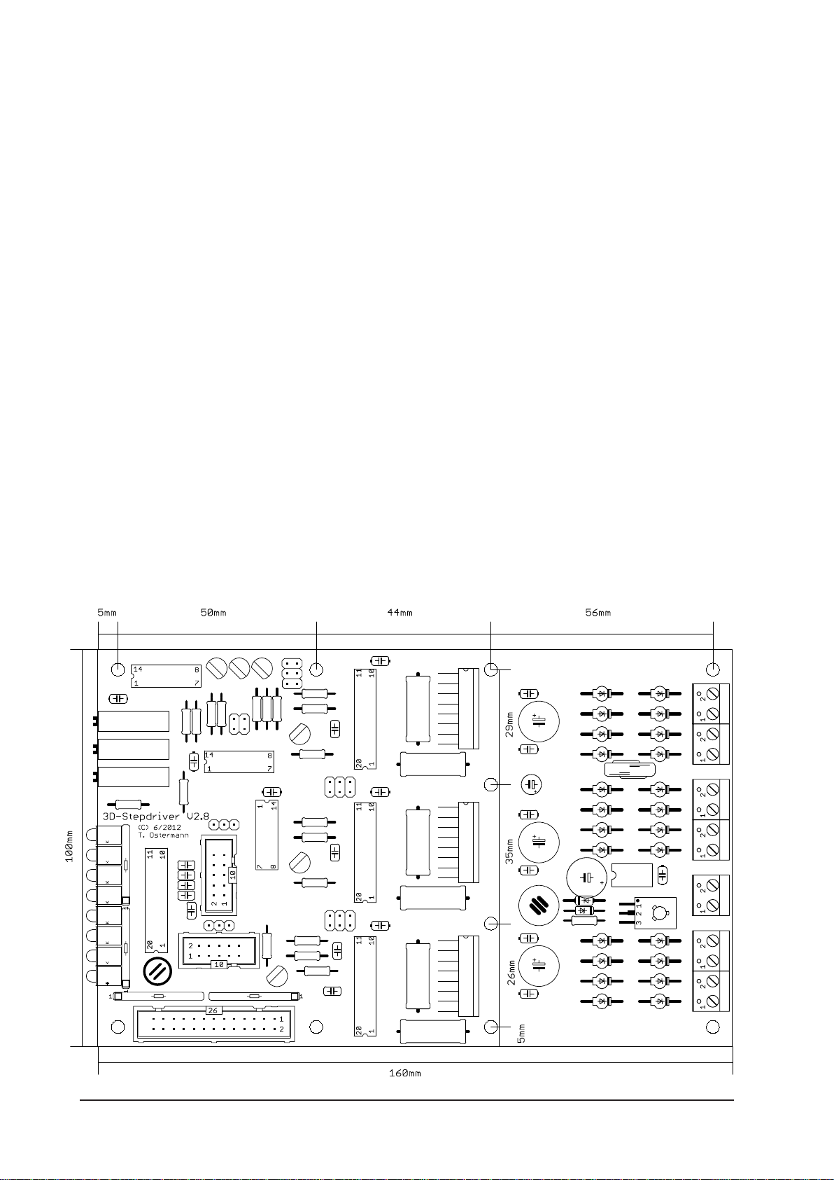
Dimensions: 100 x 160 mm
Dimensions (in mm)

www.mechapro.de • mechapro GmbH • Roermonder Str. 63 • D-52134 Herzogenrath page 9
Pinout
Pin numbering referes to standard printer port with 25pin D-SUB connector
pin no. standard signal 3D-Step
1 Strobe spindle
2 Data Bit 0 direction X
3 Data Bit 1 clock X
4 Data Bit 2 direction Y
5 Data Bit 3 clock Y
6 Data Bit 4 direction Z
7 Data Bit 5 clock Z
8 Data Bit 6 not used (optional direction C)
9 Data Bit 7 not used (optional clock C)
10 Acknowledge limit switch Z
11 Busy enable
12 Paper Out limit switch Y
13 Select limit switch X
14 Autofeed coolant
15 Error not used (opttional limit switch C)
16 Reset boost
17 Select sleep (default: low active)
18-25 GND GND
Notes

page 10 www.mechapro.de • mechapro GmbH • Roermonder Str. 63 • D-52134 Herzogenrath
Patch for the boards from the first production lot
The following connections have to be made manually due to an error in the layout, e.g. by
soldering single wires to the connection points. The pictures are showing the soldering side
of the board in the region of IC7 and between Q7 and R25 (placed under the heat sink).
Table des matières


