MCS ELECTRONICS BASCOM-AVR EM4095 RFID Reader Manuel utilisateur

© MCS Electronics , 1995-2008

BASCOM-AVR user manual
Introduction
by MCS Electronics
Dear reader.
Thank you for your interest in BASCOM.
BASCOM was "invented" in 1995. It was intended for personal usage only. I
decided to make it public as I found no other tool that was so simple to use.
Since that time, a lot of options and extensions were added. Without the help
and patience of the many users, BASCOM would not be what it is today :
"the best and most affordable tool for fast proto typing".
We hope that BASCOM will contribute in making your work with
microprocessors Easy and enjoyable.
The MCS Electronics Team

All rights reserved. No parts of this work may be reproduced in any form or by any means - graphic, electronic, or
mechanical, including photocopying, recording, taping, or information storage and retrieval systems - without the
written permission of the publisher.
Products that are referred to in this document may be either trademarks and/or registered trademarks of the
respective owners. The publisher and the author make no claim to these trademarks.
While every precaution has been taken in the preparation of this document, the publisher and the author assume no
responsibility for errors or omissions, or for damages resulting from the use of information contained in this document
or from the use of programs and source code that may accompany it. In no event shall the publisher and the author be
liable for any loss of profit or any other commercial damage caused or alleged to have been caused directly or
indirectly by this document.
Printed: 10-1-2008
BASCOM-AVR
© 2008 MCS Electronics
Publisher Special thanks to:
All the people who contributed to this document, all the forum
members that contributed in a positive way, Luciano especially, all
beta testers , and all customers.
While there is not enough space to mention all contributors, there is
one that must be mentioned : Josef Franz Vögel. He wrote the Trig
libraries, the AVR-DOS file system and the DOUBLE library.
Managing Editor
Technical Editors
Cover Designer
MCS Electronics
M.C.Alberts
M.C.Alberts
B.F.de Graaff

Part I

6BASCOM-AVR
© 2008 MCS Electronics
1EM4095 RFID Reader
Introduction
RFID technology is an exciting technology. The EM4095 chip allows us to create a
reader with little code or processor resources.
A complete KIT is available from the web shop at www.mcselec.com
This topic describes the reference design.
The data sheets you can download from:
EM4095 (chip) , EM4102 (transponder)
The circuit
As you can see from the data sheets, the EM4095 needs little external hardware. A
coil, capacitors that tune the coil for 125 KHz, are basically all that you need. IC1 is a
voltage regulator that regulates the input voltage to 5V. (you can operate it from a
9V battery). The capacitors stabilize the output voltage. The DEMOD output of the
EM4095 is connected to the microprocessor and the pin is used in input mode. The
MOD and SHD pins are connected to micro pins that are used in output mode.
The micro(mega88) has a small 32 KHz crystal so the soft clock can be used. There
are 3 switches that can be used for menu input, and there is a relay that can be used
to activate a door opener. Parallel on the relay there is a LED for a visible indication.
IC4 is a serial interface buffer so we can connect the PCB to our computer for logging
and programming. The Mega88 is delivered with a Boot loader and thus can be serial
programmed with the MCS Boot loader. That is why pin 4 of X6 (DTR) is connected
via IC4(pin 8-9) to the reset pin of the micro(pin 1).
Further there is a standard 10-pins ISP programmer connector for the USB-ISP or
STK200, and an LCD connector for an optional LCD display.

7EM4095 RFID Reader
© 2008 MCS Electronics
The PCB
Part list
Component
Value
C1
470uF/25V
C2,C3,C5,C6,C9,CDEC,CAGND
100nF (104)
C4
100uF/16V
CRES1,CRES, CDV2
1nF(102)
CDV1
47pF
CDC2,CFCAP
10nF(103)
C11,C12,C13,C14
1uF/16V
RSER
68
R4,R6
10K
R5
470
R8
47
R3
47K
R9
1K-10K pot
IC1
7805
IC2
EM4095
IC3
ATMEGA88
IC4
MAX232
20 pin IC feet, 16 pin IC feet
X1,X2
2-pin header
X3
16 pin boxed header
X4
3-pin header
X5
10-pin boxed header
X6
DB-9 female connector
T1
BC547

8BASCOM-AVR
© 2008 MCS Electronics
D1
1N4148
LED1
3 mm LED, red
K1
Relay, 5V
S1,S2,S3
switch
Q1
32768 Hz crystal
Antenna
M3x6 bolt and nut
4 rubber feet
Building the PCB
As usually we start with the components that have the lowest height. And normally
we would solder all passive components first, and insert/solder the active components
last. This to prevent damage to the active components(IC). But since the EM4095 is
only available in SMD, we need to solder this chip first. Make sure the chip is lined out
right and that pin 1 matches the small dot on the chip which is an indication for pin 1.
Then solder pin 1 and 16 so the chip can not be moved anymore. Now solder the
remaining pins. Use an iron with a small tip. When you use too much solder, and two
feet are soldered together do not panic. Just finish soldering and when ready, use
some copper braid to remove the solder between the 2 feet. This works best when
you lay the braid over the 2 pins, then push the solder iron to the braid so it will heat
up. Then after some seconds, add some solder which will get sucked into the braid.
This will in turn suck the other solder into the braid. While it does not seem logical to
add solder, it will conduct the heat better. But since the used SMD chip is relatively
large there should not be any problem.
Now mount and solder the following components :
·RSER (68 ohm)
·R3 (47K)
·R4,R6 (10 K)
·R5 (470)
·R8 (47 for LCD)
·D1 (diode 1N4148). The black line must match the line on the PCB(Kathode)
·C2,C3,C5,C6,C9,CDEC,CAGND (100 nF)
·CRES1,CRES , CDV2 (1nF)
·CDV1 (47pF)
·CDC2,CFCAP (10nF)
·28 pins IC feet for the Mega88 and 16 pins IC feet for the MAX232
·Bend the wires of IC1 and mount IC1 with the bolt and nut
·Bend the wires of the crystal and mount Q1
·S1,S2,S3 (switches)
·LED1. The square pad matches the longest wire of the LED(Anode)
·R9 (potmeter for LCD contrast)
·T1(transistor BC547)
·Boxed header X5 and X3. Notice the gap in the middle which must match with the
PCB
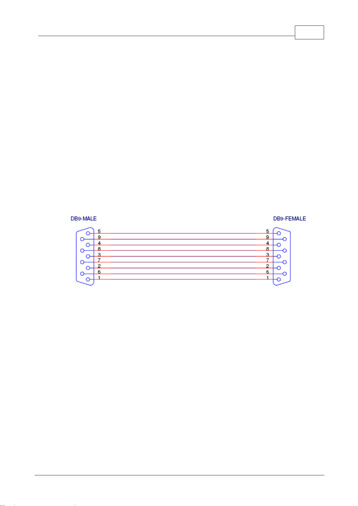
·X6 (DB9-female connector)
·K1 (relay)
·C11,C12,C13,C14 (1uF/16V)
·C4 (100uF/16V)
·X1,X2 (2 pins screw connectors)
·X4 (3 pin screw connector)
·C1 (470 uF/25V)
·4 rubber feet
Operation
Now the PCB is ready. Make sure there are no solder drops on the PCB. You can

9EM4095 RFID Reader
© 2008 MCS Electronics
measure with an Ohm-meter if there is a short circuit.
Measure pin 1 and pin 2 of IC1 (the voltage input) and pin 3 and pin 2 of IC1 (the
voltage output).
When everything is ok, insert the MAX232 and the MEGA88.
You can connect the battery cord to header X1. The red wire is the plus. Since the
circuit is not for beginners, there is no reverse polarity protection. While the 7805
does not mind a short circuit, the C1 elco might not like it.
Connect the battery and measure with a Volt meter if IC1 actual outputs 5V. If not,
check the input voltage, and for a possible shortcut.
Connect the antenna to connector X2. The PCB is now ready for use. When you have
the LCD display, connect it to the LCD header and adjust the variable resistor R9 so
you can see square blocks.
Since the chip has a boot loader, you can serial program the device. We made a
simple AN that can be used as a door opener. It has simple menu, and we can add
new tags. When a valid tag is held in front of the antenna, it will activate the relay for
2 seconds. The LED will be turned on as well.
Compile the program AN_READHITAG_EM4095.BAS and select the MCS Boot
Loader programmer. Connect a serial cable to X6 and press F4 to program.
You need a normal straight cable.
When you did not used the MCS Bootloader before, check the COM port settings
and make sure the BAUD is set to 38400 as in the following screenshot:

10 BASCOM-AVR
© 2008 MCS Electronics
You also need to set 'RESET via DTR' on the 'MCS Loader' TAB.
Now the program will start and show some info on the LCD. Each time you hold a
RFID tag before the antenna/coil, the TAG ID will be shown.
When you press S3, you can store an RFID. Press S3, and then hold the TAG before
the coil. When there is room , or the tag is new, it will be stored. Otherwise it will be
ignored. The TAG ID is also stored in EEPROM.
Now when you hold the tag before the coil, the relay is activated for 2 seconds.
The AN is very simple and you can change and extend it easily.
One nice idea from Gerhard : use one TAG as a master tag to be able to add/remove
tags.
Security
To make the code more secure you could add a delay so that a valid tag must be
received twice, so after the valid TAG, wait 1 second, and then start a new
measurement and check if the TAG is valid again.
This will prevent where a bit generator could be used to generate all possible codes.
With 64 bit times a second, it would take ages before it would work.
The other hack would be to listen with a long range 125 KHz antenna, and recording
all bits. A long range scanner would be very hard to make. It would be easier to open
the door with a crowbar.
When you open your door with this device, make sure you have a backup option like
a key in case there is no power. Also, when the door is opened by a magnetic door
opener, make sure it has the right quality for the entrance you want to protect.
Table des matières


