Maxwell AutoAnchor 710-6 Manuel utilisateur


1
AutoAnchor 710-6 Owner’s Manual
Part 1 Important Information 2
Part 2 Installation 5
Part 3 Set Up 18
Part 4 Operation 35
Part 5 Maintenance 45
Part 6 Troubleshooting 46
Index
TABLE OF CONTENTS
To the best of our knowledge the information in this manual was correct at the time
of printing. However, the AutoAnchor products are continuously being reviewed and
LPSURYHGDQGSURGXFWVSHFL¿FDWLRQVPD\EHFKDQJHGZLWKRXWQRWLFH7KHODWHVWSURGXFW
VSHFL¿FDWLRQVPD\QRWEHUHÀHFWHGLQWKLVYHUVLRQRIWKHPDQXDO7KHGRFXPHQWDWLRQ
relating to the AutoAnchor products is created in the English language and may be
WUDQVODWHGIURP(QJOLVKWRDQRWKHUODQJXDJH,QWKHHYHQWRIDQ\FRQÀLFWEHWZHHQ
WUDQVODWHGGRFXPHQWVWKH(QJOLVKODQJXDJHYHUVLRQZLOOEHWKHRI¿FLDOYHUVLRQ
AutoAnchor documents are available on the website www.autoanchor.co.nz

2
7KH$$VKRXOGRQO\EHLQVWDOOHGE\DTXDOL¿HGPDULQHHOHFWULFLDQ'RQRW
DWWHPSWWRLQVWDOOWKH$$XQOHVV\RXDUHVXLWDEO\TXDOL¿HG
7KLVPDQXDOVXSSRUWVWKHXVHRIWKH$$RQO\7KHDSSURSULDWHPDQXIDFWXUHU¶V
LQVWUXFWLRQVPXVWEHIROORZHGIRUWKHLQVWDOODWLRQDQGXVHRIWKHHTXLSPHQWWKH
$$LVVHWXSWRFRQWURO
7KHUHPXVWEHDQDOWHUQDWLYHPHWKRGDYDLODEOHWRRSHUDWHWKHZLQGODVVWKUXVWHURU
RWKHUHTXLSPHQW$IDLOXUHRIWKHZLUHOHVVOLQNZLOOUHVXOWLQORVVRIFRQWURORIWKH
HTXLSPHQWYLDWKH$$
7KH$$FDQEH¿WWHGWRPRVWYHUWLFDOZLQGODVVHV$KRUL]RQWDOZLQGODVVPD\
UHTXLUHDVHQVRUKROGHURUDFXVWRPGHVLJQHGVHQVRUZKLFKLVQRWLQFOXGHGLQWKH
standard pack. Check with your supplier or the AutoAnchor manufacturer.
)RUFKDLQFRXQWLQJWKH$$PXVWEH¿WWHGWRDZLQGODVVZLWKDGXDOGLUHFWLRQ
control box or solenoid pack.
$OOR\VWHHORUFDUERQ¿EUHZLOOUHVWULFWWKHZLUHOHVVFRPPXQLFDWLRQ7KH$$
EDVHVWDWLRQPXVWEHSRVLWLRQHGWRDYRLGWKLVRUDQDQWHQQDFDQEH¿WWHG
Contact your supplier or the AutoAnchor manufacturer for options.
,QIRUPDWLRQIRULQVWDOODWLRQDQGRSHUDWLRQRIWKH$$LVVXSSOLHGLQFOXGLQJ
SUHVHWZLQGODVVSUR¿OHOLVWVZLULQJGLDJUDPVWKH2ZQHU¶V0DQXDODQG
the Quick User Guide. All documents must be left on board for the owner.
1RQFRPSOLDQFHZLWKWKHLQVWUXFWLRQVFRXOGLPSDLURSHUDWLRQRIWKH$$WKH
ZLQGODVVWKUXVWHURURWKHUHTXLSPHQWDQGFRXOGUHVXOWLQSHUVRQDOLQMXU\DQGRU
damage to the boat.
1RQFRPSOLDQFHZLWKWKHLQVWUXFWLRQVZLOOQHJDWHWKHPDQXIDFWXUHU¶VZDUUDQW\
7KH$$PDQXIDFWXUHUDQGVXSSOLHUDFFHSWQROLDELOLW\IRUSHUVRQDOLQMXU\RU
property damage resulting from failure to follow the installation and operation
LQVWUXFWLRQVRUWKHXVHRIWKH$$LQDZD\WKDWPD\FDXVHDFFLGHQWVRU
damage or that may violate the law.
$OOWKHWHFKQLFDODQGFDEOHVSHFL¿FDWLRQVPXVWEHFKHFNHGDQGDGKHUHGWRDQG
ZLULQJGLDJUDPVPXVWEHIROORZHGZLWKRXWPRGL¿FDWLRQ
%HIRUHXVHWKH$$PXVWEHFRUUHFWO\VHWXSIRUDOOWKHHTXLSPHQWLWLVWRFRQWURO
DQGWHVWHGLQDVDIHHQYLURQPHQW7KH$$ZLOOQRWFRXQWFRUUHFWO\LIWKH
windlass selection is wrong or the windlass is not standard (eg it is installed
with a different chainwheel or motor).
$OOLQVWDOODWLRQVPXVWEHFDUULHGRXWLQDFFRUGDQFHZLWK86&*$%<&100$DQG
%0($UHTXLUHPHQWV
:KHQWKLVSURGXFWUHDFKHVWKHHQGRILWVXVHIXOOLIHLWPXVWEHGLVSRVHGRILQ
accordance with local regulations.
PART 1 IMPORTANT INFORMATION
READ BEFORE INSTALLING OR USING THE AUTOANCHOR

3
TECHNICAL SPECIFICATIONS
Parameter AA710 Remote Console AA702 Base Station
3RZHU6XSSO\ [$$9%DWWHULHV 99'&
0D[LPXP9ROWDJH 30V DC
Current Consumption 1$ P$
2XWSXW0D[LPXP
&XUUHQW'UDZ
1$ 9'&$
9'&$
The system has internal current
limiting and thermal shutdown.
2XWSXW0LQLPXP
&XUUHQW'UDZ
1$ 9'&P$
9'&P$
IP Rating ,3 ,3
2SHUDWLQJ7HPSHUDWXUH
Range o)WRo)o&WRoC) o)WRo)o&WRoC)
:LUHOHVV7UDQVPLVVLRQ *+],60%DQG,(((&RPSOLDQW%LW8QLTXH,'
:LUHOHVV5DQJH 7\SLFDO0LQLPXPPIW5DQJHGHSHQGVRQLQVWDOODWLRQ
2XWSXWV 6
6\VWHP6XSSRUWV 8SWREDVHVWDWLRQVDQGFRQVROHV
5RGH&KDLQ2QO\ 6WDLQOHVVRUJDOYDQLVHGVWHHO
Rode - Rope and Chain 0XVWKDYHDPLQLPXPRIIWPRIFKDLQ&KDLQPXVWEH
JDOYDQLVHGVWHHO5RSHVKRXOGEHDJRRGTXDOLW\Q\ORQDQFKRU
URSH7\SHRUHTXLYDOHQW
'&ZLQGODVVHVUHTXLUHDGXDOGLUHFWLRQVROHQRLG

4
RADIO FREQUENCY COMPLIANCE
FCC Information:
7KLVGHYLFHFRPSOLHVZLWK3DUWRIWKH)&&5XOHV2SHUDWLRQLVVXEMHFWWRWKHIROORZLQJ
WZRFRQGLWLRQVWKLVGHYLFHPD\QRWFDXVHKDUPIXOLQWHUIHUHQFHDQGWKLVGHYLFHPXVW
accept any interference received, including interference that may cause undesired
operation.
0RGL¿FDWLRQVQRWH[SUHVVO\DSSURYHGE\WKHPDQXIDFWXUHUFRXOGYRLGWKHXVHU¶VDXWKRULW\WR
RSHUDWHWKLVHTXLSPHQW
This device generates, uVHVDQGFDQUDGLDWHUDGLRIUHTXHQF\HQHUJ\DQGLIQRWLQVWDOOHG
DQGXVHGLQDFFRUGDQFHZLWKWKHPDQXIDFWXUHU¶VLQVWUXFWLRQVPD\FDXVHKDUPIXO
interference to radio communications.
ESTI Information (CE):
7KLVGHYLFHLVFRPSOLDQWZLWKWKHHVVHQWLDOUHTXLUHPHQWVRIWKH577('LUHFWLYH(&
PHHWLQJWKH(XURSHDQKDUPRQL]HG(0&DQGORZYROWDJHVDIHW\VWDQGDUGV
ELECTROMAGNETIC COMPATIBILITY (EMC)
FCC Information:
7KLVGHYLFHFRPSOLHVZLWK&)53DUWRI)&&5XOHVIRU&ODVV%HTXLSPHQW
ESTI Information (CE):
7KLVGHYLFHPHHWVWKHUHOHYDQWVWDQGDUGVVHWRXWLQ(XURSHDQ6WDQGDUG(1IRU
PDULWLPHQDYLJDWLRQDQGUDGLRFRPPXQLFDWLRQHTXLSPHQWDQGV\VWHPVThese standards
are intended to provide reasonable protection against interference by other emission
generating products on the boat. Compliance with these standards is no guarantee that
interference will not occur in a particular installation. The installation instructions must be
followed to minimise the potential for interference.
Note: If shielded cable is not used for the sensor connections this will compromise the
(0&DQGPD\LQYDOLGDWHWKHZDUUDQW\
$$HTXLSPHQW$$EDVHVWDWLRQDQG$$UHPRWHFRQVROHPXVWEHLQVWDOOHGDW
OHDVWIWPDZD\IURPDQ\HTXLSPHQWWUDQVPLWWLQJRUFDEOHVFDUU\LQJUDGLRVLJQDOVHJ
9+)UDGLRVPRGL¿HGVLQHZDYHLQYHUWHUVFDEOHVDQGDQWHQQDVRUUDGDUDQWHQQDVDQGDW
OHDVWIWPDZD\IURPDQ\66%HTXLSPHQW$$FDEOHVPXVWEHLQVWDOOHGDWOHDVW
IWPPDZD\IURPVXFKLWHPV

5
PART 2 INSTALLATION
Drilling the Deck: %HIRUHGULOOLQJLQWRWKHGHFNHQVXUHWKHUHLVQRWKLQJEHORZWKHGHFN
WKDWFRXOGEHGDPDJHGDQGWKDWDQ\KROH\RXGULOOZLOOQRWZHDNHQWKHERDW¶VVWUXFWXUH'ULOO
DKROHPP´GLDPHWHUWKURXJKWKHGHFN(QVXUHWKLVKROHLVGLUHFWO\LQOLQHZLWK
the sensor hole in the deckplate.
2.1 INSTALLATION TO OPERATE A WINDLASS
2.1.3 SENSOR INSTALLATION OVERVIEW
Vertical Windlasses: 7KHVHQVRULV¿WWHGLQWKHGHFNSODWH6RPHGHFNSODWHVDUHSUHGULOOHG
IRUWKHVHQVRU2WKHUVKDYHDGLPSOHRUPDUNWRVKRZZKHUHWKHVHQVRUVKRXOGEH¿WWHG
,IWKHZLQGODVVLVQRWIDFWRU\GULOOHGGULOODKROHPP´GLDPHWHUWKURXJKWKH
ZLQGODVVGHFNSODWH6HHWKHLQVWUXFWLRQVIRU\RXUVSHFL¿FZLQGODVVW\SH
Hori]ontal Windlasses: Sometimes it is not possible to ¿t the sensor to a hori]ontal
windlass or it ma\need to be ¿tted b\the windlass manufacturer. Before starting
check with the AutoAnchor manufacturer or supplier that it is possible to ¿t the
sensor to \our windlass. You ma\need a special ¿tting.
2.1.2 MAGNET INSTALLATION OVERVIEW
Check before starting. <RXUFKDLQZKHHOPD\EHSUH¿WWHGZLWKDPDJQHWRUSUHGULOOHG
UHDG\IRU\RXWR¿WWKHPDJQHW
Magnet Polarity: 1RWUHOHYDQWZKHQXVLQJWKHJUH\$$VHQVRURUDUHHGVZLWFK
VHQVRU,IUHWUR¿WWLQJXVLQJWKHEODFN$$VHQVRUWKHVRXWKSROHPDUNHGVLGHRI
the magnet must face the sensor.
Magnet Seal:,QVHUWWKHPDJQHWLQWRWKHKROHDQGFRYHULWZLWKDPLQLPXPRIPPRIHSR[\
WRSURWHFWLWDJDLQVWFRUURVLRQ6HH)LJRQSDJH
Magnet Size and Position: 5HIHUWRWKHLQVWUXFWLRQVIRU\RXUVSHFL¿FZLQGODVVW\SH
2.1.1 MAGNET AND SENSOR INSTALLATION
PLEASE READ BEFORE COMMENCING INSTALLATION
Correct magnet and sensor installation is critical for successful AutoAnchor
operation.
The AutoAnchor can be installed on vertical windlasses, drum winches and most
horizontal windlasses. Installation differs depending on the windlass type and on the
rode (all-chain or rope and chain). Please follow the instructions for your windlass
and rode. If it is not possible to comply with these instructions please check with the
AutoAnchor manufacturer or your supplier for other options or if you are not sure how to
proceed.
6HHwww.autoanchor.co.nz for contact information.
6
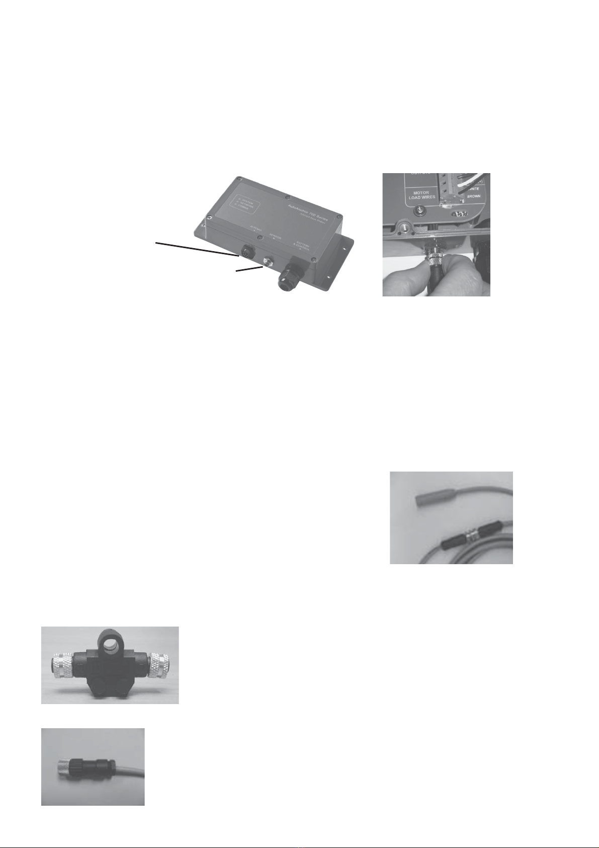
3DUW0DOH)LHOG&RQQHFWRU
3DUW)HPDOH)LHOG&RQQHFWRU
,IWKHUHLVQRSOXJRQWKHVHQVRUFDEOHDWWDFKWKH$$¿HOG
connector to the wires and use the connecting cable as above.
2.1.4 PLUG AND PLAY SENSOR CABLE
7KH$XWR$QFKRUSOXJDQGSOD\VHQVRUFDEOHLVFRUHWLQQHGVKLHOGHGFDEOH,WPXVWEH
XVHGWRFRQQHFWWKHVHQVRUWRWKHFRQVROHXQLW(QVXUHWKHFRQQHFWRUVDUH¿UPO\VFUHZHG
together.
The warranty does not apply if the sensor cable plugs are removed.
7KHVHQVRUFDEOHLV¿WWHGZLWKDIHPDOHSOXJWRFRQQHFWGLUHFWWRWKHPDOHFRQQHFWRURQWKH
$$EDVHVWDWLRQ,IDORQJHUOHQJWKLVUHTXLUHGVHQVRUFRQQHFWLQJFDEOHZLWKDPDOH
SOXJDWHDFKHQGLVDYDLODEOHLQWKHIROORZLQJOHQJWKV
P IW 3DUW
PIW 3DUW
P IW 3DUW
P IW 3DUW
P IW 3DUW
P IW 3DUW
$PPDOHIHPDOHFDEOH3DUWSOXVDJHQGHUFKDQJHU3DUWZLOOEHUHTXLUHG
to connect the extension cable to the base station.
Field Connectors
Sensor Connection:7KHVHQVRULVSOXJJHGGLUHFWLQWRWKH$$EDVHVWDWLRQ'RQRW
leave the cable hanging loose, it must be tied in place with cable ties. Extension cable,
JHQGHUFKDQJHUVDQG¿HOGFRQQHFWRUVDUHDYDLODEOHLIUHTXLUHG
6HQVRU3OXJ
Fitting the Sensor: 'RQRWIRUFHWKHVHQVRULQWRWKHKROH+DPPHULQJWKHVHQVRUKHDG
can damage the internal electronics. Ensure the sensor head is positioned so that it will not
EHKLWE\WKHFKDLQZKHHOGXULQJZLQGODVVRSHUDWLRQDQGWKDWLWLVDWOHDVWPPIWDZD\
IURPWKHEDWWHU\DQGPRWRUFDEOHV6HFXUHWKHVHQVRUXVLQJDJRRGTXDOLW\QHXWUDOFXUH
VLOLFRQHRUDVWURQJDGKHVLYHHJ6LNDÀH[RU0
Connecting 2 cables together:
,I\RXQHHGWRH[WHQGWKHFDEOHOHQJWKFDEOHVFDQEHMRLQHG
WRJHWKHUXVLQJ3DUW*HQGHU&KDQJHU
Antenna Plug

7
Dual Installation with Other AA Products
8VHWKH7DGDSWRU3DUWDQGWKHP0DOH)HPDOHH[WHQVLRQFDEOH
3DUW
2.1.5 REED SWITCH SENSORS
6RPHZLQGODVVHVDUHVXSSOLHGSUH¿WWHGZLWKDUHHGVZLWFKVHQVRU5HHGVZLWFKVHQVRUV
PXVWKDYHDPP[PPPDJQHWDQGWKHJDSEHWZHHQWKHUHHGVZLWFKVHQVRU
DQGWKHPDJQHWPXVWEHDPLQLPXPRIPPDQGDPD[LPXPRIPP7KLVVHQVRUUHTXLUHV
D¿HOGFRQQHFWRU
The AutoAnchor will operate with a reed switch sensor for all-chain rode. If using
combination rope and chain rode the reed switch sensor provides a reasonably accurate
count of rode deployed but on retrieval the display may be incorrect because it cannot
allow for the stretch in the rope.
)RUDQDFFXUDWHURSHDQGFKDLQFRXQWWKHUHHGVZLWFKVHQVRUVKRXOGEHUHSODFHGZLWKWKH
$$JUH\VHQVRU
2.1.6 SENSOR TUNING
:KHQWKH$XWR$QFKRULVFRPSOHWHO\LQVWDOOHGWKHVHQVRUPXVWEHWXQHG6HHWKH
LQVWUXFWLRQVRQSDJH

8
Magnet Fit'ULOODKROHPP´GLDPHWHUDQGPP´GHHSWR¿WWKH
magnet in the underside of a spoke in the bottom of the chainwheel. Cover the magnet
ZLWKDPLQLPXPRIPPHSR[\7KHPDJQHWVKRXOGEHDOLJQHGZLWKWKHVHQVRU6HH)LJ
2.1.7 INSTALLATION ON A VERTICAL WINDLASS - CHAIN ONLY
Magnet Size:6WDQGDUGVL]HLVPP[PPP7KLVPD\EHUHSODFHGZLWKWKH
VPDOOHUPP[PPPDJQHWLIUHTXLUHGIRU\RXUZLQGODVV
Gap Between the Sensor and Magnet:
6HQVRU 0DJQHW6L]H Gap
$$*UH\6HQVRU PP[PP 0LQLPXPPP0D[LPXPPP
$$*UH\6HQVRU PP[PP 0LQLPXPPP0D[LPXPPP
$$%ODFN6HQVRU $OO0DJQHWV 0LQLPXPPP0D[LPXPPP
5HHG6ZLWFK6HQVRU PP[PP 0LQLPXPPP0D[LPXPPP
Refer to the Overview Notes on page 5 before starting installation.
Sensor Connection:,GHDOO\WKHVHQVRUVKRXOGEHSOXJJHGGLUHFWO\LQWRWKH$$EDVH
VWDWLRQ,IORQJHUFDEOHLVUHTXLUHGXVHWKH$$PPDOHIHPDOHH[WHQVLRQFDEOH3DUW
RURQHRIWKH$$VWDQGDUGPDOHPDOHH[WHQVLRQFDEOHVSOXVWKHPFDEOHDQGD
JHQGHUFKDQJHU(QVXUHWKHFRQQHFWRUVDUH¿UPO\VFUHZHGWRJHWKHU6HHWKHLQIRUPDWLRQ
on page 6.
Loose cable should be tied in place with cable ties and kept clear of chain.
Sensor Position:7KH$$EODFNVHQVRUDQGWKHUHHGVZLWFKVHQVRUPXVWEH¿WWHGGLUHFOW\
LQOLQHZLWKWKHPDJQHWLQWKHFKDLQZKHHO6HH)LJDERYH7KH$$JUH\VHQVRUPD\EH
¿WWHGXSWRPPRXWRIDOLJQPHQW7KHJDSEHWZHHQWKHVHQVRUDQGPDJQHWPXVWEHDV
per the table below.
Note: If it is not possible to
align the sensor and magnet
exactly the AAgrey sensor may
EH¿WWHGXSWRPPRXWRI
alignment. The AA black sensor
and the reed switch sensor must
be directly aligned.
)LJ$OOVHQVRUV
6HDOZLWKPLQLPXPPPHSR[\
0DJQHW
6HQVRU
Chainwheel
'HFNSODWH

9
Magnet Fit: 6RPHZLQGODVVHVDUHSUHGULOOHGDQGRWKHUVQHHGDVSHFLDO¿W3OHDVHFKHFN
ZLWK\RXUVXSSOLHU7KHXVXDO¿WLVDVIROORZV'ULOODKROHPP´GLDPHWHUDQG
PP´GHHSLQWRDVSRNHLQWKHWRSRIWKHFKDLQZKHHO&RYHUWKHPDJQHWZLWKD
PLQLPXPRIPPHSR[\7KHPDJQHWDQGVHQVRUPXVWEHDOLJQHGVRWKDWWKHDQFKRUURGH
SDVVHVEHWZHHQWKHP6HH)LJV
6HQVR
r
0DJQHW
)LJ )LJ
2.1.8 INSTALLATION ON A VERTICAL WINDLASS - ROPE & CHAIN
)RUDQDFFXUDWHURSHDQGFKDLQFRXQWWKH rode must run between the sensor and
PDJQHW,I\RXUZLQGODVVLVSUH¿WWHGZLWKDPDJQHWLQWKHERWWRPRIWKHFKDLQZKHHO\RX
QHHGWRUHPRYHLWDQG¿WDQHZPDJQHWLQWKHWRSRIWKHFKDLQZKHHO5HIHUWR)LJV
Magnet Size:PP;PPPDJQHW$QPP[PPPDJQHWPD\EH
used on smaller windlasses. Check with your supplier.
Sensor Position7KHVHQVRUPXVWEH¿WWHGLQWRWKHGHFNSODWHZLWKLQWKHVHQVRUSRVLWLRQ
UDQJHDWWKHVWHUQHQGRIWKHZLQGODVV6HH)LJ,WPXVWDOVREHDOLJQHGZLWKWKHPDJQHW
so that the rode passes between the sensor and the magnet. The centre of the magnet
DQGWKHFHQWUHRIWKHVHQVRUPD\EHXSWRPPRXWRIGLUHFWDOLJQPHQW6HH)LJ7KH
gap between the sensor and magnet must be as per the table below.
Chainwheel
'HFNSODWH
)LJ
6HQVRU0DJQHWPD\EHXSWR
PPRXWRIGLUHFWDOLJQPHQW
PP
6HQVRU
0DJQHW
6HQVRU
0DJQHW
Sensor Position Rope & Chain Vertical Windlasses
Gap Between the Sensor and Magnet
Sensor Magnet Size Gap
$$*UH\6HQVRU PP[PP 0LQLPXPPP0D[LPXPPP
$$*UH\6HQVRU PP[PP 0LQLPXPPP0D[LPXPPP
Refer to the Overview Notes on page 5 before starting installation.
Sensor Connection: If longer cable is
UHTXLUHGWKH$XWR$QFKRUSOXJDQGSOD\
sensor extension cable must be used
WRFRQQHFWWKHVHQVRUWRWKH$$
base station. Ensure the connectors
DUH¿UPO\VFUHZHGWRJHWKHU6HHWKH
information on page 6.
Loose cable should be tied in place
with cable ties and kept clear of
chain.
6HDOZLWKPLQLPXPPPHSR[\
0DJQHW
)LJ
6HQVRU3RVLWLRQ
Range
90oBow
Stern
Rode
Anchor
Locker
Chainwheel
Ce manuel convient aux modèles suivants
1
Table des matières
Manuels Télécommande populaires d'autres marques

Panasonic
Panasonic EUR7622KB0 Manuel utilisateur

Bang & Olufsen
Bang & Olufsen Beo4 Manuel utilisateur

Sunwave Tech.
Sunwave Tech. RemoteComm SRC-7000 Manuel utilisateur

Multiplex
Multiplex PROFI TX 9 Manuel utilisateur

One Remote
One Remote RMB4 Manuel utilisateur

FUTABA
FUTABA 9ZAP - PART2 Manuel utilisateur


