Max 1200FS pro Manuel utilisateur

4009963
Residential/Commercial
Brushless DC Slide Gate Operators
Made in USA
SAFETY SENSORS REQUIRED
CONFORMS TO UL STD 325
UL CLASS - I, II, III, IV
CERTIFIED TO CAN/CSA STD
C22.2 NO. 247
MATRIX III
Installation Guide for
MAX 1
2
00FS
pro
max 1700FS pro
Fail Safe Slide Gate Operator
www.max.us.com
Version 2c

2
UL 325 2018 Standard - MAX 1200 FS PRO/1700 FS PRO Matrix III Install Version 2c
Safety - 1
ul 325 compliant installation
requirements
a) Install the gate operator only when:
a) N’installez l’ouvre-barrière que si :
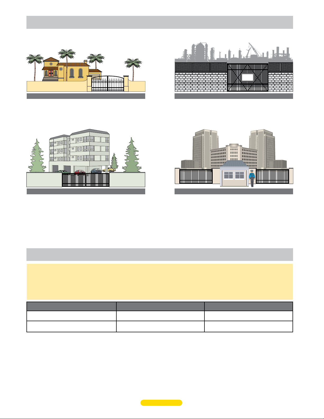
1) The operator is appropriate for the construction of the gate and the usage Class of the gate,
1) l’ouvre-barrière est approprié pour la structure et la classe d’utilisation de la barrière;
2) All openings of a horizontal slide gate are guarded or screened from the bottom of the gate to a minimum of 1.83 m (6 ft) above the ground
to prevent a 57.2 mm (2-1/4 inch) diameter sphere from passing through the openings anywhere in the gate, and in that portion of the
adjacent fence that the gate covers in the open position,
2) toutes les ouvertures de la barrière coulissante sont protégées ou grillagées du bas de la porte jusqu’à unminimum de 1,83 m (6 pi) du sol
si bien qu’une sphère de 57,2 mm (2 1/4 po) de diamètre ne peut passer par une ouverture au niveau de la barrière et de la portion de la
clôture adjacente que la barrière couvre en position ouverte;
3) All exposed pinch points are eliminated or guarded, and
3) tous les points de pincement sont éliminés ou protégés;
4) Guarding is supplied for exposed rollers.
4) des protections sont fournies pour les galets exposés.
b) The operator is intended for installation only on gates used for vehicles. Pedestrians must be supplied with a separate access opening. The
pedestrian access opening shall be designed to promote pedestrian usage. Locate the gate such that persons will not come in contact with the
vehicular gate during the entire path of travel of the vehicular gate.
b) L’ouvre-barrière est destiné à n’être installé que sur des barrières utilisées pour les véhicules. Il faut fournir une autre voie d’accès aux
piétons. La voie d’accès pour les piétons doit être conçue pour favoriser le passage des piétons. Placez la barrière de sorte que personne ne
puisse entrer en contact avec la barrière pour les véhicules sur l’ensemble de sa trajectoire.
c) The gate must be installed in a location so that enough clearance is supplied between the gate and adjacent structures when opening and
closing to reduce the risk of entrapment. Swinging gates shall not open into public access areas.
c) Pour réduire les risques de coincement lors de l’ouverture et de la fermeture, la barrière doit être installée dans un endroit où la barrière et
les structures avoisinantes sont suffisamment éloignées l’une de l’autre. Les barriers battantes ne doivent pas ouvrir dans une zone d’accès
public.
d) The gate must be properly installed and work freely in both directions prior to the installation of the gate operator. Do not over-tighten the
operator clutch or pressure relief valve to compensate for a damaged gate.
d) La barrière doit être bien installée et fonctionner librement dans les deux directions avant d’entreprendre l’installation de l’ouvre-barrière.
Ne serrez pas trop l’embrayage ou la soupape de surpression de l’ouvre-barrière pour compenser une barrière endommagée.
e) For gate operators utilizing Type D protection:
e) Pour les ouvre-barrières qui utilisent des protections de type D :
1) The gate operator controls must be placed so that the user has full view of the gate area when the gate is moving,
1) les commandes de l’ouvre-barrière doivent être placées de sorte que l’utilisateur voit l’ensemble de la zone de la barrière lorsque cette
dernière est en mouvement;
2) The placard as required by 62.1.6 shall be placed adjacent to the controls,
2) l’étiquette requise selon la clause 62.1.6 doit être placée à côté des commandes;
3) An automatic closing device (such as a timer, loop sensor, or similar device) shall not be employed, and
3) un dispositif de fermeture automatique (comme une minuterie, une boucle de détection ou un dispositif similaire) ne doit pas être utilisé;
4) No other activation device shall be connected.
4) aucun autre appareil d’activation ne doit être connecté.
f) Controls intended for user activation must be located at least 1.83 m (6 ft) away from any moving part of the gate and where the user is
prevented from reaching over, under, around or through the gate to operate the controls.
f) Les commandes destinées à l’activation par l’utilisateur doivent être situées à au moins 1,83 m (6 pi) des pieces mobiles de la barrière et à
un endroit où l’utilisateur ne peut pas atteindre les commandes par le dessus, par le dessous, par les côtés et au travers de la barrière.
Exception: Emergency access controls only accessible by authorized personnel (e.g. fire, police, EMS) may be placed at any location in the
line-of-sight of the gate.
Exception : Les commandes d’accès d’urgence accessibles au personnel autorisé seulement (p. ex. pompier, policier, SMU) peuvent être
placées à tout endroit dans le champ de visibilité de la barrière.

3
UL 325 2018 Standard - MAX 1200 FS PRO/1700 FS PRO Matrix III Install Version 2c
Safety - 2
ul 325 compliant installation
requirements continued
g) The Stop and/or Reset button must be located in the lineof-sight of the gate. Activation of the reset control shall not cause the operator to
start.
g) Le bouton d’arrêt, le bouton de réenclenchement ou ces deux boutons doivent être situés dans le champ de visibilité de la barrière.
L’activation des commandes de réenclenchement ne doit pas mettre en marche l’ouvrebarrière.
h) A minimum of two (2) WARNING SIGNS shall be installed, in the area of the gate. Each placard is to be visible by persons located on the
side of the gate on which the placard is installed. Also see 62.1.1.
h) Au moins deux panneaux de mise en garde doivent être installés dans la zone de la barrière. Chaque étiquette doit être visible des
personnes situées de chaque côté de la barrière sur laquelle l’étiquette est installée. Voir aussi la clause 62.1.1.
i) For gate operators utilizing a non-contact sensor in accordance with 32.1.1:
i) Pour les ouvre-barrières qui fonctionnent avec des capteurs sans contact conformément à la clause 32.1.1 :
1) See instructions on the placement of non-contact sensors for each Type of application,
1) Voir les instructions sur le positionnement des capteurs sans contact pour chaque type d’utilisation.
2) Care shall be exercised to reduce the risk of nuisance tripping, such as when a vehicle, trips the sensor while the gate is still moving, and
2) Des précautions doivent être prises pour réduire les risques de déclenchement inutile, comme lorsqu’un véhicule déclenche le capteur alors
que la barrière est encore en mouvement.
3) One or more non-contact sensors shall be located where the risk of entrapment or obstruction exists, such as the perimeter reachable by a
moving gate or barrier.
3) Un capteur sans contact ou plus doit être situé où il existe un risque de coincement ou d’obstruction, comme dans l’espace que peut
occuper la barrière lorsqu’elle est en mouvement.
j) For a gate operator utilizing a contact sensor in accordance with 32.1.1:
j) Pour les ouvre-barrières qui fonctionnent avec des capteurs de contact conformément à la clause 32.1.1 :
1) One or more contact sensors shall be located where the risk of entrapment or obstruction exists, such as at the leading edge, trailing edge,
and postmounted both inside and outside of a vehicular horizontal slide gate.
1) Au moins un capteur de contact doit être situé où il existe un risque de coincement ou d’obstruction, comme sur le bord d’ouverture, sur le
bord de fermeture et sur les poteaux montés sur l’intérieur ou l’extérieur d’une barrière coulissante pour véhicules.
2) One or more contact sensors shall be located at the bottom edge of a vehicular vertical lift gate.
2) Au moins un capteur de contact doit être situé sur le bord inférieur d’une barrière levante pour véhicules.
3) One or more contact sensors shall be located at the pinch point of a vehicular vertical pivot gate.
3) Au moins un capteur de contact doit être situé au point de pincement d’une barrière à pivot vertical pour véhicules.
4) A hardwired contact sensor shall be located and its wiring arranged so that the communication between the sensor and the gate operator is
not subjected to mechanical damage.
4) Un capteur de contact doit être installé et câblé de sorte à éviter que la communication entre le capteur et l’ouvrebarrière soit gênée par des
dommages mécaniques.
5) A wireless device such as one that transmits radio frequency (RF) signals to the gate operator for entrapment protection functions shall be
located where the transmission of the signals are not obstructed or impeded by building structures, natural landscaping or similar obstruc-
tion. A wireless device shall function under the intended end-use conditions.
5) Un dispositif sans fil, comme un appareil qui transmet des signaux de radiofréquence (RF) à l’ouvre-barrière pour prévenir le coincement,
doit être situé à un endroit où la transmission des signaux ne sera pas obstruée ou gênée par des structures, des arbres ou d’autres obstacles
similaires. Un dispositif sans fil doit fonctionner selon les conditions d’utilisation finale prévues.
6) One or more contact sensors shall be located on the inside and outside leading edge of a swing gate. Additionally, if the bottom edge of a
swing gate is greater than 152 mm (6 inches) but less than 406 mm (16 inches) above the ground at any point in its arc of travel, one or more
contact sensors shall be located on the bottom edge.
6) Au moins un capteur de contact doit être situé sur les bords d’ouverture intérieur et extérieur d’une barrière battante. De plus, si le dessous
d’une barrière battante est situé à plus de 152 mm (6 po) mais à moins de 406 mm (16 po) du sol à l’un des points de sa trajectoire, au moins
un capteur de contact doit être situé sur le bord inférieur.
7) One or more contact sensors shall be located at the bottom edge of a vertical barrier (arm).
7) Au moins un capteur de contact doit être situé sur le bord inférieur d’une barrière verticale (bras).

4
UL 325 2018 Standard - MAX 1200 FS PRO/1700 FS PRO Matrix III Install Version 2c
Safety - 3
IMPORTANT SAFETY INSTRUCTIONS WARNING – To reduce the risk of injury or death:
INSTRUCTIONS DE SÉCURITÉ IMPORTANTES AVERTISSEMENT – Pour réduire les risques de blessures et de mort :
1. READ AND FOLLOW ALL INSTRUCTIONS.
1. LISEZ ET SUIVEZ TOUTES LES INSTRUCTIONS.
2. Never let children operate or play with gate controls. Keep the remote control away from children.
2. Ne laissez jamais les enfants manoeuvrer les commandes de la barrière ou jouer avec celles-ci. Laissez la télécommande hors de la portée
des enfants.
3. Always keep people and objects away from the gate. NO ONE SHOULD CROSS THE PATH OF THE MOVING GATE.
3. Tenez toujours à l’écart de la barrière toute personne ou tout objet avoisinant. IL NE FAUT JAMAIS PASSER DANS LA TRAJECTOIRE D’UNE
BARRIÈRE EN MOUVEMENT.
4. Test the gate operator monthly. The gate MUST reverse on contact with a rigid object or stop when an object activates the non-contact
sensors. After adjusting the force or the limit of travel, retest the gate operator. Failure to adjust and retest the gate operator properly can
increase the risk of injury or death.
4. Vérifiez le fonctionnement de l’ouvre-barrière une fois par mois. Le sens de la course DOIT s’inverser lorsque la barrière entre en contact
avec un objet dur ou la barrière DOIT s’arrêter lorsqu’un objet active les capteurs sans contact. Vérifiez à nouveau l’ouvre-barrière après tout
réglage de la force de déclenchement ou du seuil de fin de course. Un réglage incorrect de l’ouvre-barrière ou l’omission de vérifier à nouveau
le fonctionnement de l’ouvre-barrière peut causer des blessures, voire la mort.
5. Use the emergency release only when the gate is not moving.
5. Ne déclenchez le dispositif de désaccouplement d’urgence que lorsque la barrière ne bouge pas.
6. KEEP GATES PROPERLY MAINTAINED. Read the user’s manual. Have a qualified service person make repairs to gate hardware.
6. ASSUREZ-VOUS QUE LA BARRIÈRE EST CORRECTEMENT ENTRETENUE. Lisez le manuel de l’utilisateur. Confiez la réparation du matériel
de la barrière à un technicien qualifié.
7. The entrance is for vehicles only. Pedestrians must use separate entrance.
7. La voie d’accès est réservée aux véhicules seulement. Les piétons doivent utiliser une voie d’accès différente.
8. SAVE THESE INSTRUCTIONS.
8. CONSERVEZ CES INSTRUCTIONS.
important safety information

CLASS I
Residential Vehicular Gate Operator - A vehicular gate operator
(opener or system) intended for use in a home of one to four
single family dwellings, or a garage or parking area associated
therewith.
CLASS II
Commercial/General Access Vehicular Gate Operator - A
vehicular gate operator (opener or system) intended for use in
a commercial location or building such as a multi-family
housing unit (five or more single family units) hotel, garages,
retail store or other building servicing the general public.
CLASS III
Industrial/Limited Access Vehicular Gate Operator - A
vehicular gate operator (opener or system) intended for uses
in an industrial location, loading dock area or other location
not intended to service the general public.
CLASS IV
Restricted Access Vehicular Gate Operator - A vehicular gate
operator (opener or system) intended for use in a guarded
industrial location or buildings such as airport security area or
other restricted access locations not servicing the general
public, in which unauthorized access is prevented via
supervision by security personnel.
SECURITY
AUTHORIZED
PERSONNEL
ONLY
ul 325 model classifications
A - Inherent entrapment protection system.
B1 - Provision for connection of a non-contact sensor
(photoelectric sensor or the equivalent).
B2 - Provision for connection of a contact sensor
(edge device or the equivalent).
C - Inherent adjustable clutch or pressure relief device.
D - Provision for connection of an actuating device
requiring continuous pressure to maintain opening
or closing motion of the gate.
Gate Type Class I & II
Swing Gate A, B1*, B2*, C, D
Slide Gate A, B1*, B2*, D
Class III & IV
A, B1*, B2*, C, D
A, B1*, B2*, D
ul 325 required entrapment protection
*B1 and B2 means of entrapment protection must be MONITORED.
This vehicular gate operator must be installed with at least two independent entrapment protection means as specified in the table and
definitions below.
The same type of device shall not be used for both entrapment protection means. Use of a single device to cover both the opening and
closing directions is in accordance with the requirement, however, a single device is not required to cover both directions. This operator
has been provided with type A entrapment protection. The installer is required to install additional entrapment protection devices in each
entrapment area.
5
UL 325 2018 Standard - MAX 1200 FS PRO/1700 FS PRO Matrix III Install Version 2c
Safety - 4

Safety Loop
Entrapment Area
Entrapment Area
Moving Gate Can Cause
Serious Injury or Death
KEEP CLEAR! Gate may move at any time
without prior warning.
Do not let children operate the gate or play
in the gate area.
This entrance is for vehicles only.
Pedestrians must use separate entrance.
Automatic Exit
Loop
Safety Loop
The operator is intended for use on a VEHICULAR slide gate ONLY. It is intended to be used WITH appropriate entrapment
protection safety devices and in-ground vehicle loop detection system. Pedestrians MUST use a separate entrance.
Pedestrians MUST use a separate entrance.
Gate operator IS NOT intended to be used on a PEDESTRIAN gate.
In-Ground Loops: Help
protect the gate operator
from accidentally opening
and/or closing on vehicles
in the gate’s path
OPENING Direction Photocell:
Helps guard against the opening
gate from entrapment between
wall and gate.
Entrapment sensors must be installed where entrapment or pinch point exist.
A minimum of TWO entrapment protection sensors MUST be installed, ONE in EACH
direction of gate travel or operator will NOT function.
Physical Stops:
Install on BOTH ends of
gate rail to limit the travel
of gate to the fully open
and fully closed positions.
OPENING Direction Reverse Edge: Helps guard against the opening gate from entrapment.
OPENING Direction Reverse Edge: Helps guard against the
opening gate from entrapment between wall and gate.
CLOSING Direction Photocell: Helps
guard against the closing gate from
entrapment.
CLOSING Direction Reverse Edge: Helps guard
against the closing gate from entrapment.
Wire Mesh: 2” x 2” at least 6 ft high. Installed on gate when the space between the gate pickets is MORE than 2 1/4”.
Gate Pickets: The space between the gate pickets should be LESS than 2 1/4” or wire mesh should be installed.
Guide Rollers: Must be installed for safety.
Warning Signs: Should be installed on BOTH sides of gate area and easily visible.
Physical Stop
intended use of
slide gate operator
UL 325 2018 Standard - MAX 1200 FS PRO/1700 FS PRO Matrix III Install Version 2c
Safety - 5a

If gate pickets are farther apart than 2-1/4 inch,
Maximum Controls HIGHLY RECOMMENDS installing wire mesh on the ENTIRE gate AND on
that portion of the adjacent fence that the gate covers in the open position (when necessary).
UL 325 Requirements:
All openings of a horizontal slide
gate are guarded or screened from
the bottom of the gate to a
minimum of 6 feet (1.83 m) above
the ground to prevent a 2-1/4 inch
(57.2 mm) diameter sphere from
passing through the openings
anywhere in the gate, and in that
portion of the adjacent fence that
the gate covers in the open
position, all exposed pinch points
are eliminated or guarded, and
guarding is supplied for exposed
rollers.
gate safety installation
DO NOT install a opening device accessible through the gate.
It MUST be mounted a minimum of 6 feet away from ALL
moving parts of the gate and in line-of-sight of the gate.
Install it high enough to keep out of reach of small children.
Opening Device Requirements
Wire Mesh
Greater than 2-1/4 inch
UL 325 2018 Standard - MAX 1200 FS PRO/1700 FS PRO Matrix III Install Version 2c
Safety - 5b

MAX 1700FS
pro/1200FS
pro specs
Step-By-Step Installation
Operator Placement (Standard)
Connect Chain to Gate (Standard)
Rear Mounting Position (Alternate)
Connect Chain to Gate (Rear Pos)
AC Input Power
Ground Operator
Opening Direction/ID Plug/Operator
Entrapment Protection Wiring
Program Virtual Limit Sensors
Learn Gate Positions
Adjust ERD Reverse Sensor
Loops & Loop Detectors
Matrix III Settings
Wiring Opening Device Options
Learn Unlearned Sensor Inputs
1
2
3
4
5
6
6
7-8
9
10
10
11
11
12
12
Table of Contents
Troubleshooting
USB Black Box Port
Test Entrapment Sensors
Gate Cycling Troubleshooting
Matrix III LED Troubleshooting
Commonly Used Safety Sensors
Wiring Overview
Optional Magnetic Limit Sensors
Optional Solar Power
19
19
20
21-22
26”
14 1/2”19”
7 1/2”
UL 325 Class of Operation - Class I, II, III, IV
Gate Type - Vehicular Slide Gate
Max Gate Length - 25ft/1200FS PRO, 50 ft/1700FS PRO
Max Gate Weight -1200FS PRO / 1200 lbs Level Gate
1700FS PRO / 1700 lbs Level Gate
Opening Time - Selectable speed control (MAX - 12 inch per second)
Dipswitch selectable 18" per second 1700FS only (Class III & IV)
Cycles per Hour AC Power - Continuous
Battery Back-Up Cycles (Batteries fully charged) - Approximately 100 cycles
Input AC Power/Amps - Switchable: 115VAC / 6 Amp, 1 phase
or 230VAC / 2 Amp, 1 phase
Motor: 1200 FS PRO: 1/2 HP 24VDC Brushless (6 million cycles)
1700 FS PRO: 1 HP 24VDC Brushless (6 million cycles)
Chain Size - #40
Operating Temperature: -4°F to 158°F (-20°C to 70°C)
Entrapment Protection:
- UL 325 Type A Inherent (ERD sensor)
- Inputs for NORMALLY CLOSED (N.C.) and 10K Type
UL 325 Type B1 (photo cell)
and Type B2 (sensing edge)
NOTE: The number of gate cycles using ONLY battery back-up power will vary depending on
the weight of the gate, the gate length, the operating condition of the gate, temperature and
the amount of charge the batteries have at the beginning of the battery power only operation.
Gate Safety
UL 325 Compliant Installation Requirements
UL 325 Model Classifications
Indended Use of Slide Gate Operator
Safety-1-3
Safety-4
Safety-5a-5b
Page Additional Features cont’d
Partial Open Programming
Dropping the Chain - Gate Tamper is Armed (ON)
Dual Gate Operators Wiring
Gate Disable Feature
16
16
17
18
Page
TWO Entrapment protection
sensors MUST be installed,
ONE in EACH direction of
gate travel or operator will
NOT function.
1A
1A
1B
1B
2
3
4
5
6
7
8
9
10
11
12
UL 325 2018 Standard - MAX 1200 FS PRO/1700 FS PRO Matrix III Install Version 2c
Additional Features Page
13
13
Omron E3K-R10K4 UL325 2018
Omron E3K-R10K4 UL325 2016
Omron E3K-R10K4 UL325 2018
EMX WEL-200 Wiring
WEL-200 Programming
EMX-RET Wiring
EMX IRB-MON Single Gate Wiring
EMX IRB-MON Dual
Miller RBAND Monitored Wireless
23
24
25
26
27
28
29
30
31
36-39
Programming
DIP-Switch Settings
Manual Release Options
Gate Tamper Feature
1435
34
15
Transmitter Solutions iGaze 32-33

CLOSING Photocell Beam
OPENING Photocell Beam
Reflector
CLOSING
Sensing
Edge with
Wireless
Module
Operator Placement (standard)
1A
V-Rail Physical Stop
Concrete Pad
Operator
Position on
Concrete Pad
Operator in Front Position (Standard)
Outside Property
Inside Property
24”
24”
Wireless
Module
Gate in Closed Position
4”4”
2” Gate Frame
10.5”
10.5”
6.2”
6.75”
7.5”7.5”
6.75” Cover
1.5”
4”5”
6.5”
The gate must be properly installed and work freely in both directions prior to installation of the gate operator.
•REQUIRED - AC input power wire.
•REQUIRED - Entrapment protection OPENING and CLOSING photocell
and/or sensing edges.
•In-ground loop wires.
Conduit Guidelines and Suggestions
8.625”
12.75”
Conduit
Area
Input Power
Conduit Run
Concrete Pad
Check local building
codes in your area for
depth of concrete
before installation.
Guide rollers MUST be Installed to keep gate upright.
6” above ground to avoid flooding.
Concrete Depth Note: The heavier the gate, the deeper the concrete pad should be. At least two feet recommended for heavier gate.
Secure gate operator to
concrete pad with four
(4) 1/2” x 3” (min)
sleeve anchors.
1/2
Wireless
Module
CLOSING
Sensing
Edge with
Wireless
Module
Guide Rollers
Safety sensors (Photocell or contact EDGE) must be
installed in BOTH opening and closing direction of gate
movement where entrapment or pinch point exist. TWO
safety sensor min. (N.C. or 10K type) MUST be installed or
operator will NOT function. All sensors must be UL325,
2018 compliant. See pages 7-8.
UL 325 2018 Standard
IMPORTANT: Physical stops MUST
be installed on BOTH ends of rail to
keep gate from traveling off of rail.
IMPORTANT:
Physical Stop
MUST be installed
See next page for chain information.
Choose either Front Mounting Position (Standard) or Rear Mounting Position (Alternate).
1A 1B
OPENING Sensing Edge with Wireless Module
Operator MUST be level.
step-by-step installation
1
UL 325 2018 Standard - MAX 1200 FS PRO/1700 FS PRO Matrix III Install Version 2c

1A
YES
YES
6”
13.5”13.5”
7.5”7.5”
Concrete Pad
Idler Wheels
Idler Wheel
Chain
Bracket
Side Chain Guide
Side Chain Guide
IMPORTANT: Operator and chain MUST be parallel to gate or the idler
wheels could fail. Use the “Fine Tune” adjustment on the gate bracket
connection bolt and make sure the chain runs through the idler wheels
without binding on the side chain guides.
Minimum distance between the drive gear and gate is 4”.
Chain brackets MUST
remain same height as
idler wheels.
Operator is too far from gate.
Chain is NOT parallel to gate.
Operator is too close to gate.
Chain is NOT parallel to gate.
Operator is NOT parallel to gate.
Chain is NOT parallel to gate.
DO NOT mount chain
bracket too high on gate.
NO
NO
YES
YES
YES
YES
Drive
Gear
NOTE: The chain should
sag no more than one (1)
inch per 10 feet of travel.
Do not over tighten the
chain.
NOTE: 25 ft of #40 nickel plated chain included.
4” Min4” Min
Top View of Operator
Back View of Operator
NO
NO
Gate Bracket
Fine Tune
Adjustment
4” Min4” Min
NO
NO
NO
NO
NO
NO
Chain
Bracket
Chain
Bracket
Chain
Bracket
Chain
Bracket
DO NOT mount chain bracket too low on gate.
NO
NO
Factory installed
position
Operator in Front Position (Standard)
IMPORTANT: Physical stops MUST be
installed on BOTH ends of gate rail to
keep gate from traveling off of rail.
connect chain to gate (standard)
2
UL 325 2018 Standard - MAX 1200 FS PRO/1700 FS PRO Matrix III Install Version 2c
Ce manuel convient aux modèles suivants
1
Table des matières
Autres manuels Max ouvre-porte


