Matrix SATATYA Project Series Manuel utilisateur
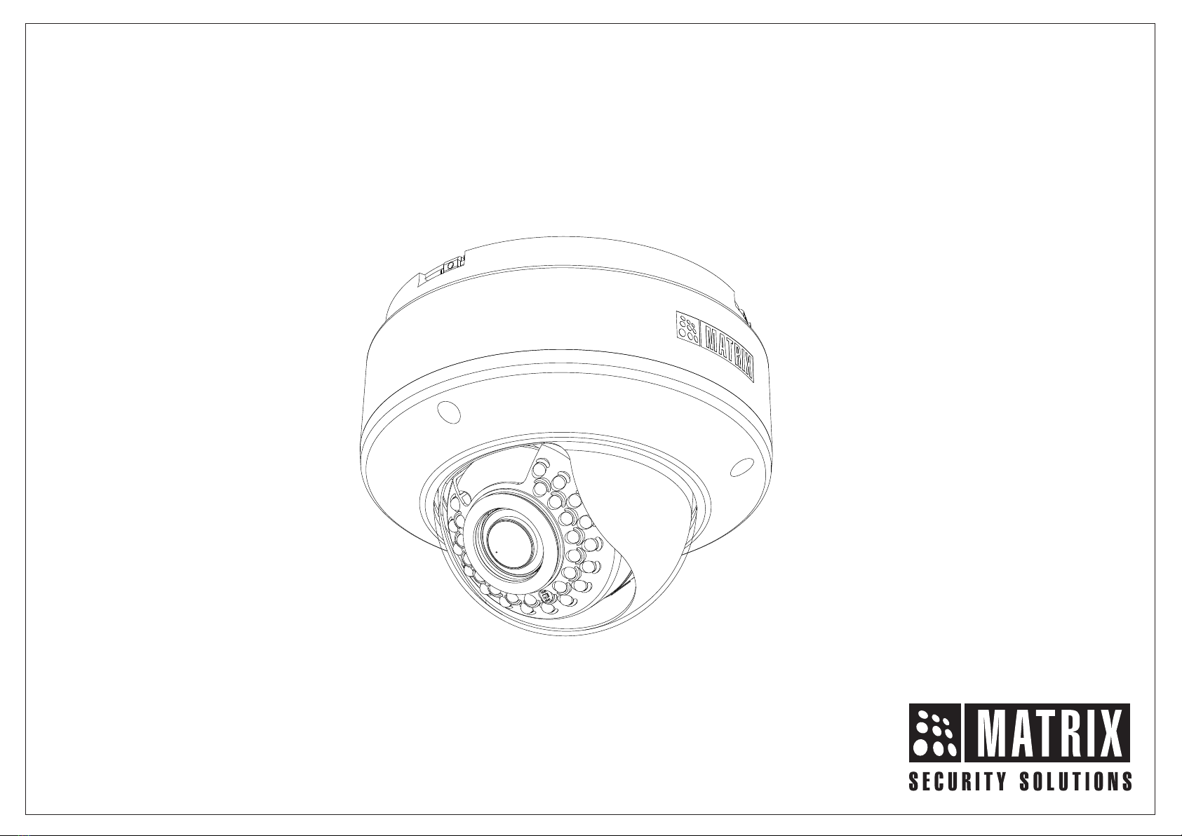
SATATYA Project Dome IP-Camera
The Persistent Vision

Safety Instructions
Cautions
Warning
Consignes de sécurité
These instructions are intended to ensure that the user can
use the product correctly to avoid danger or property loss.
•Ensure that the power supply voltage is correct before using the
camera.
•Avoid placing cables too close to magnetic or high voltage
devices, to reduce undesirable image noise.
•Do not touch sensor modules with fingers. For cleaning use
‘clean cloth’ and wipe it gently.
•Do not mount the camera with the lens facing the sun or bright
light to prevent damage to the sensor.
•Do not expose the camera to temperatures below or beyond its
operating temperature.
•Do not mount the camera near a radiator or a heater.
•In the use of the product, you must be in strict compliance with
the electrical safety regulations of the region and nation.
•Do not connect several devices to one power adapter as it may
cause over-heating or fire hazard.
•If smoke, odour or noise rise from the device, turn off the power at
once and unplug the power cable, and contact the nearest service
center.
•To prevent electrical shock, turn off power supply before making
electrical connections.
Précautions
Attention
Ces instructions ont pour but de garantir que l'utilisateur peut Utilisez
le produit correctement pour éviter tout danger ou perte de propriété.
•Vérifiez que la tension d'alimentation est correcte avant d'utiliser
l'appareil photo.
•Évitez de placer des câbles trop près d'une tension magnétique
ou élevée périphériques, pour réduire le bruit d'image indésirable.
•Ne touchez pas les modules de capteur avec les doigts. Pour le
nettoyage, utilisez nettoyer chiffon et essuyez-le doucement.
•Ne montez pas l'appareil photo avec l'objectif dirigé vers le soleil
ou vers lumière pour éviter d'endommager le capteur.
•N'exposez pas l'appareil photo à des températures inférieures ou
supérieures à ses température de fonctionnement.
•Ne montez pas la caméra à proximité d'un radiateur ou d'un
appareil de chauffage.
•Dans l'utilisation du produit, vous devez être en stricte conformité
avec les réglementations de sécurité électrique de la région et de
la nation.
•Ne connectez pas plusieurs périphériques à un seul adaptateur
secteur, provoquer une surchauffe ou un risque d'incendie.
•Si de la fumée, des odeurs ou du bruit émanent de l'appareil,
éteignez-le une fois, débranchez le câble d'alimentation et
contactez le service d'assistance le plus proche centre.
•Pour éviter un choc électrique, éteignez l'alimentation avant de
connections electriques.

6
7
5
41
2
3
What your Package Contains
Things you will Need
Contents
Accessing Reset Pin and SD card slot
Accessing via Web Browser
4
8
9
Camera Variants
Installation
Network Configuration
Installing Mounting Template
Mounting the Camera on Wall/Ceiling
Adjusting the Camera Angle
Please read this guide first for correct installation and retain it for future reference. The information
in this guide is prevailing at the time of publication. However, Matrix Comsec reserves the right to
make changes in product design and specifications without prior notice.
Copyright
All rights reserved. No part of this document may be copied or reproduced in any form or by any
means without the prior written consent of Matrix Comsec.
Warranty
Limited Warranty. Valid only if primary protection is provided, mains supply is within limit and
protected, and environment conditions maintained within product specifications. Complete
warranty statement is available on our website:
www.matrixvideosurveillance.com
Technical Specification
IP66 Protection Accessory Installation
Know your Camera
5
5
5
Adjusting Focus and Zoom in Varifocal Cameras 1. Mounting Ring
2. Base Plate
3. Cable Assembly
4. Hole for Mounting
5. Base Plate grove for fitting
Mounting Ring
6. Camera Body
7. Lens Enclosure
The Standard variant consists of 2 connectors: Power Connector and
Ethernet Connector (POE).
The Premium variant consist of 6 connectors: Power Connector,
Ethernet Connector (POE), Audio IN, Audio OUT, Alarm IN and
Alarm OUT.
4
Know your Camera
Figure1
Mounting the Camera on False Ceiling
PAN, Tilt Movement
Powering the Camera
10
11
14
17
18
20
22
23
24
25
29

What your Package Contains
Things you will Need
Camera Variants
The Bullet Cameras are available in following variants:
1. Standard Variant used for General Surveillance in
Discipline/Safety Precaution.
2. Premium Variant used for Objective Surveillance in Entry/Exit
Monitoring, Periphery Monitoring, Productivity Monitoring, Unethical
Practices Monitoring.
ŸSATATYA Dome IP Camera Unit
ŸWall Mounting Template
ŸWall Mounting Screws with Screw Grip (3 nos.)
ŸAllen Key
ŸCable Accessories to compliant for IP66
ŸCeiling Support Plate
ŸCeiling Support Plate Screws (M4x35 pan-PH)
•A Power Drill, Screwdriver Set, Pliers, Wire-cutter, Ladder.
•Necessary Cabling
•A Power Supply with the recommended output voltage of 12V DC.
Use an adapter to connect the camera to the power outlet.
5
You can capture near and broader view with lens of 2.8mm and
4.0 mm focal length. For example it can be used in ATM and
Elevators.
With lens of 6 mm focal length, far and narrow view can be
captured. For example it can be used in corridors or long
passage to capture long view.
6
The 5MP Camera variants are listed in below table,
Type of
Lens
Focal
Length
Fixed
4.0mm
6.0mm
CIDR50FL40CWS
Premium
Standard
CIDR50FL60CWS
Manual
Varifocal
2.8-12
mm
Motorized
Varifocal
NA CIDR50MVL12CWP
CIDR50VL12CWS
2.8mm CIDR50FL28CWS
2.8-12
mm
CIDR50FL28CWP
CIDR50FL40CWP
CIDR50FL60CWP
NA
Fixed
Fixed

1. This product is intended to be supplied by a UL listed power
supply unit marked “Class 2” or “LPS” or “PS2” and rated 12VDC,
2A min.
2. The wired LAN hub providing Power over the Ethernet (PoE) in
accordance with IEEE 802-3af shall be a UL listed device with the
output evaluated as a limited power source as defined in UL60950-
1 or Ps2 as defined in UL62368-1.
Installation Instruction
7
Step 1: Select a Location
Select a suitable location for your camera to enable coverage of the
intended surveillance area. The location should preferably be a flat
surface, such as a wall or a ceiling.
You can install the camera where cables are running through the
interior of the wall or ceiling. Else cabling has to be done through
POE.
Installation
Before you start:
You can insert SD card in camera to store recordings during network
failover and to upload image or clip as a result of event trigger.
See page 22 to view the SD card slot in camera.
8
Step 2: Prepare for Installation
Ensure that the necessary cabling to connect the camera to LAN port
and Power outlet are in place. The connecting cables from the
monitoring site should be ready at the installation site.
Please make sure,
ŸThe device in the package is in good condition and all the
assembly parts are included.
ŸAll the related equipments are powered-off before installation.
ŸThe wall or ceiling is strong enough to support the weight of
camera.

Step 4: Mounting the Camera
Figure 3
A. On Wall/Ceiling
•Stick the Mounting Template on the desired installation surface.
•Drill three 7.5mm diameter holes through the markings of the
Mounting Template on Wall or Ceiling. (Drill 50mm diameter hole
also if installing on false ceiling)
•Insert the screw grips in the holes you drilled.
Step 3: Installing Mounting Template
Mounting Ring
Mounting Template
7.5mm
diameter
50mm
diameter
•Align the screw holes on the base plate with those you drilled on
the installation surface.
•To avoid cable damage, take the Power, Ethernet, Audio IN,
Audio OUT, Alarm IN, Alarm OUT cables of the camera through
the cable hole on the base plate, see Figure 3.
•If the cabling is concealed, prior to the installation pull the cable
off the hole drilled on the installation surface.
•Now secure the base plate of the camera to the mounting ring.
Interlock the mounting ring slit to the groove on the base plate,
see Figure 4.
•Turn the camera body clockwise to fit in the slit of mounting ring.
•Finally fit the base plate with three M3x4 Grub screws, see
Figure 5.
Figure 2
10
9

Grove
Slit
Mounting ring
Grub screws
Base Plate
Figure 4
Figure 5
B. On False Ceiling (Recommended Method)
Figure 6
False Ceiling
Ceiling Support Plate
For installing Dome Camera on false ceiling follow the below
mentioned steps,
•Install the mounting template on the false ceiling.
•Drill the holes through the markings of the mounting template
on the false ceiling.
•By this you will get one 50mm diameter and three 7.5mm
diameter holes on the false ceiling.
•Insert the Ceiling Support Plate through the 50mm diameter
hole as shown in Figure 6.
•Place the Ceiling support plate over the false ceiling with keeping
the clinching nuts towards the holes on mounting template.
•Move Ceiling Support Plate manually as the holes on Ceiling
Support Plate align with the holes (7.5mm) on mounting template
as illustrated in Figure 7.
Figure 7
Clinching Nut
12
11

Figure 9
Figure 8
Mounting Ring
Screws
•Align the screw holes of the mounting ring with the holes
(7.5mm) on mounting template and insert the screws through
the false ceiling as illustrated in Figure 8.
•It is recommended to use M4 Pan-PH screws of length 35mm.
•Tighten the screws.
•Finally fix the Camera to the mounting ring as illustrated in
Figure 9.
Step 3: IP66 Protection Accessory Installation
1. By default your camera contains the LAN connector fitted by IP66
protection accessory.
3. Rotate the middle part of IP66 assembly in anticlockwise direction
to detach the IP66 accessory from the LAN connector.
2. The IP66 protection assembly consist of tail end, middle part,
“IO” ring and LAN connector as shown below.
Tail end Middle
Part “O”ring LAN
Connector
Power cable
IP66 protection accessory
14
13

Do not remove the “O” ring from its place.
LAN Connector
IP66 accessory
4. Loosen the tail end of the IP66 accessory by rotating it in
anticlockwise direction.
Ethernet cable
5. Insert the ethernet cable from behind. Then tighten the “tail end”
by rotating in clockwise direction to its maximum and crimp the
RJ45 connector.
6. Insert male RJ45 connector into female connector part. Then
tighten the middle part by rotating in clockwise direction.
16
15

Step1: Opening Lens cover
Adjusting Camera Angle
Figure 10
•Use the Allen Key to loosen the Retainer screws on 3 sides of
camera body.
•The retainer screws will still remain loosely connected.
•Open the lens casing body.
•Now you can adjust the camera angle.
Retainer
screws
Alley Key
LED: CLASS1 (Category RS1)
Step2: PAN, TILT movement
Thumb screws
Figure 11
•Loosen thumb screws on both sides of lens for PAN movement, see
Figure 11.
•For PAN movement you can move the camera to 100 degrees on
one side, see Figure 12. To capture other side view, you have to
open the camera body from the mounting ring, turn the body and
mount to other side.
18
17
Never look at the transmit laser while the power is on. Never
look directly at the fiber ports and the fiber cable ends when
they are powered on.
Use of controls or adjustment to the performance or procedure
other than those specified herein may result in hazardous laser
emission.
Autres manuels pour SATATYA Project Series
1
Ce manuel convient aux modèles suivants
2
Table des matières
Autres manuels Matrix Caméra de sécurité

Matrix
Matrix SATATYA PZCR50ML42CWP Guide de l'utilisateur

Matrix
Matrix SATATYA PZCR20ML25CWP Guide de l'utilisateur

Matrix
Matrix SATATYA PZCR50ML42CWP Manuel utilisateur

Matrix
Matrix SATATYA Professional Series Manuel utilisateur

Matrix
Matrix SATATYA Professional Series Manuel utilisateur

Matrix
Matrix SATATYA PZCR20ML33CWP Guide de l'utilisateur

Matrix
Matrix SATATYA PZCR20ML25CWP Manuel utilisateur


