Matatakitoyo Torque Tools WTT-1301 Manuel utilisateur

I
FCC Part 15
EMI TEST REPORT
of
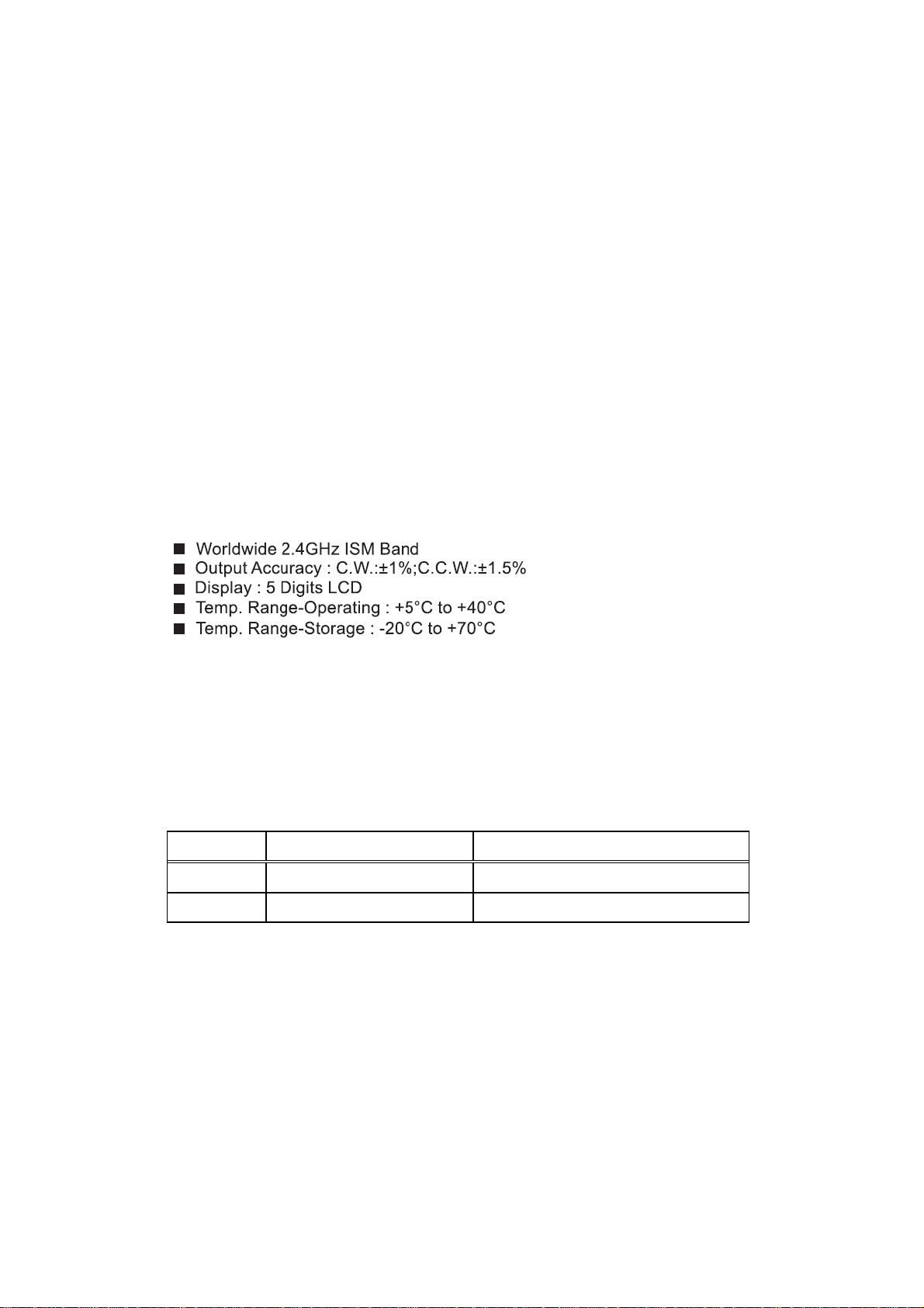
E.U.T. : Wireless Display
MODEL : WTT-1301
FCC ID. : 2AC96WDP
Frequency Range : 2402MHz~2418MHz
for
APPLICANT : MATATAKITOYO TOOL Co., Ltd.
ADDRESS : No.21, Lane 97, Her-Tzuo St., Feng-Yuan Dist.,
Taichung City, Taiwan
Test Performed by
ELECTRONICS TESTING CENTER, TAIWAN
NO. 34. LIN 5, DINGFU VIL., LINKOU DIST.,
NEW TAIPEI CITY, TAIWAN, 24442, R.O.C.
TEL : (02)26023052 FAX: (02)26010910
http:// www.etc.org.tw; e-mail:[email protected]
Report Number : 16-09-RBF-027

ETC Report No. : 16-09-RBF-027 FCC ID: WTT-1301
II
TEST REPORT CERTIFICATION
Applicant : MATATAKITOYO TOOL Co., Ltd.
No.21, Lane 97, Her-Tzuo St., Feng-Yuan Dist., Taichung City,
Taiwan
Manufacturer : MATATAKITOYO TOOL Co., Ltd.
No.21, Lane 97, Her-Tzuo St., Feng-Yuan Dist., Taichung City,
Taiwan
Description of EUT
a) Type of EUT : Wireless Display
b) Trade Name : ---
c) Model No. : WTT-1301
d) Power Supply : Battery DC 4.5V
e) Frequency Range : 2402MHz~2418MHz
Regulation Applied : FCC Rules and Regulations Part 15 Subpart C
I HEREBY CERTIFY THAT: The data shown in this report were made in accordance with the
procedures given in ANSI C63.10-2013, and the energy emitted by the device was founded to be
within the limits applicable. I assume full responsibility for accuracy and completeness of these
data.
Note: 1. The result of the testing report relate only to the item tested.
2. The testing report shall not be reproduced expect in full, without the written approval of
ETC.
Summary of Tests
Test Results
Radiated Emission Pass
Conducted Emission N/A
Band Edge Requirement Pass
Duty Cycle N.A.
20dB Bandwidth Pass

ETC Report No. : 16-09-RBF-027 FCC ID: WTT-1301
III
Date Test Item Received : Sep. 20, 2016
Date Test Campaign Completed : Nov. 04, 2016
Date of Issue : Nov. 21, 2016
Test Engineer :
(Kazuma Ho, Engineer )
Approve & Authorized Signer :
S. S. Liou, Section Manager
EMC Dept. II of ELECTRONICS
TESTING CENTER, TAIWAN

ETC Report No. : 16-09-RBF-027 FCC ID: WTT-1301
IV
Table of Contents Page
Cover Page…………………………………………………………………………………………..I
TEST REPORT CERTIFICATION…………………………………………………………….…..II
Table of Contents…………………………………………………………………………………..IV
1 GENERAL INFORMATION ...................................................................................................... 1
1.1 Product Description ...................................................................................................................... 1
1.2 Characteristics of Device ............................................................................................................. 1
1.3 Test Methodology ........................................................................................................................ 1
1.4 Test Facility .................................................................................................................................. 1
2 PROVISIONS APPLICABLE ..................................................................................................... 2
2.1 Definition ..................................................................................................................................... 2
2.2 Requirement for Compliance ....................................................................................................... 3
2.3 Restricted Bands of Operation ..................................................................................................... 5
2.4 Labeling Requirement .................................................................................................................. 5
2.5 User Information .......................................................................................................................... 6
3. SYSTEM TEST CONFIGURATION ......................................................................................... 7
3.1 Justification .................................................................................................................................. 7
3.2 Devices for Tested System ........................................................................................................... 7
4 RADIATED EMISSION MEASUREMENT .............................................................................. 8
4.1 Applicable Standard ..................................................................................................................... 8
4.2 Measurement Procedure ............................................................................................................... 8
4.3 Measuring Instrument ................................................................................................................ 10
4.4 Radiated Emission Data ............................................................................................................. 11
4.4.1 RF Portion ......................................................................................................................................... 11
4.4.2 Radiated Emissions in Restricted Bands ............................................................................................ 15
4.4.3 Other Emissions ................................................................................................................................. 17
4.5 Field Strength Calculation ......................................................................................................... 21
4.6 Photos of Radiation Measuring Setup ........................................................................................ 22
5 CONDUCTED EMISSION MEASUREMENT ....................................................................... 24
5.1 Standard Applicable ................................................................................................................... 24
6 ANTENNA REQUIREMENT ................................................................................................... 25
6.1 Standard Applicable ................................................................................................................... 25
6.2 Antenna Construction................................................................................................................. 25
7 BAND EDGES MEASUREMENT ............................................................................................ 26
7.1 Standard Applicable ................................................................................................................... 26

ETC Report No. : 16-09-RBF-027 FCC ID: WTT-1301
V
7.2 Measurement Procedure ............................................................................................................. 26
7.3 Measurement Equipment ........................................................................................................... 27
7.4 Measurement Data ..................................................................................................................... 27
8. DYTY CYCLE............................................................................................................................ 30
8.1 Standard Applicable ................................................................................................................... 30
8.2 Measurement Equipment ........................................................................................................... 30
8.3 Measurement Data ..................................................................................................................... 30
9. BANDWIDTH OF EMISSION ................................................................................................. 32
9.1 Applicable Standard ................................................................................................................... 32
9.2 Measurement Procedure ............................................................................................................. 32
9.3 Measurement Equipment ........................................................................................................... 33
9.4 Measurement Data ..................................................................................................................... 33
ETC Report No. : 16-09-RBF-027 Sheet 1 of 36 Sheets
FCC ID: 2AC96WDP
1
1 GENERAL INFORMATION
1.1 Product Description
a) Type of EUT : Wireless Display
b) Trade Name : ---
c) Model No. : WTT-1301
d) Power Supply : Battery DC 4.5V
e) Frequency Range : 2402MHz~2418MHz
1.2 Characteristics of Device
The EUT is a Wireless Display.
1.3 Test Methodology
Both conducted and radiated emissions were performed according to the procedures
illustrated in ANSI C63.10-2013. Other required measurements were illustrated in separate
sections of this test report for details.
Measurement Software
Software Version Note
e3 Version 6.100618b Radiated Emission Test
e3 Version 6.100421 Conducted Emission Test
1.4 Test Facility
Location of the Test site: No.34, Lin 5, Dingfu Vil., Linkou Dist., New Taipei City, Taiwan
24442, R.O.C.
Designation Number: TW2628.

ETC Report No. : 16-09-RBF-027 Sheet 2 of 36 Sheets
FCC ID: 2AC96WDP
2
2 PROVISIONS APPLICABLE
2.1 Definition
Unintentional radiator:
A device that intentionally generates and radio frequency energy for use within the device, or
that sends radio frequency signals by conduction to associated equipment via connecting
wiring, but which is not intended to emit RF energy by radiation or induction.
Class A Digital Device:
A digital device which is marketed for use in commercial or business environment; exclusive
of a device which is market for use by the general public, or which is intended to be used in
the home.
Class B Digital Device :
A digital device which is marketed for use in a residential environment notwithstanding use
in a commercial, business of industrial environment. Example of such devices that are
marketed for the general public.
Note : A manufacturer may also qualify a device intended to be marketed in a commercial,
business, or industrial environment as a Class B digital device, and in fact is
encouraged to do so, provided the device complies with the technical specifications
for a Class B Digital Device. In the event that a particular type of device has been
found to repeatedly cause harmful interference to radio communications, the
Commission may classify such a digital device as a Class B Digital Device,
Regardless of its intended use.
Intentional radiator:
A device that intentionally generates and emits radio frequency energy by radiation or
induction.

ETC Report No. : 16-09-RBF-027 Sheet 3 of 36 Sheets
FCC ID: 2AC96WDP
3
2.2 Requirement for Compliance
(1) Conducted Emission Requirement
For an intentional radiator that is designed to be connected to the public utility (AC)
power line, the radio frequency voltage that is conducted back onto the AC power line on
any frequency or frequencies within the band 150kHz to 30MHz shall not exceed the
limits in the following table, as measured using a 50MH/50 ohms line impedance
stabilization network (LISN). Compliance with the provisions of this paragraph shall be
based on the measurement of the radio frequency voltage between each power line and
ground at the power terminal. The lower limit applies at the band edges.
Frequency
MHz
Quasi Peak
dBμV
Average
dBμV
0.15 - 0.5 66-56 56-46
0.5 - 5.0 56 46
5.0 - 30.0 60 50
(2) Radiated Emission Requirement
For unintentional device, according to §15.109(a), except for Class A digital devices, the
field strength of radiated emissions from unintentional radiators at a distance of 3 meters
shall not exceed the following values:
Frequency
MHz
Distance
Meters
Radiated
dBμV/m
Radiated
μV/m
30 - 88 3 40.0 100
88 - 216 3 43.5 150
216 - 960 3 46.0 200
Above 960 3 54.0 500
For intentional device, according to §15.209(a), the general requirement of field strength
of radiated emissions from intentional radiators at a distance of 3 meters shall not exceed
the above table.

ETC Report No. : 16-09-RBF-027 Sheet 4 of 36 Sheets
FCC ID: 2AC96WDP
4
For intentional radiator device, per §15.249(a), the field strength of emissions shall
comply with the following :
Frequency
MHz
Distance
Meters
Fundamental
dBμV/m mV/m
Harmonic
dBμV/m μV/m
902 - 928 3 94 50 54 500
2400 - 2483.5 3 94 50 54 500
5725 - 5875 3 94 50 54 500
24000 - 24250 3 108 250 68 2500
In accordance with §15.249(e), limits shown in above table are based on average limits
for frequencies above 1000 MHz, and frequencies below 1000 MHz are based on quasi
peak. However, the peak field strength of any emission shall not exceed the maximum
permitted average limits by more than 20 dB.
(3) Spurious in Out Band Requirement
For intentional device, according to §15.249 (d), emissions radiated outside of the
specified frequency bands, except for harmonics, shall be attenuated by at least 50 dB
below the level of fundamental or to the general radiated emission limits in §15.209.
(4) Antenna Requirement
For intentional device, according to §15.203, an intentional radiator shall be designed to
ensure that no antenna other than that furnished by the responsible party shall be used
with the device.

ETC Report No. : 16-09-RBF-027 Sheet 5 of 36 Sheets
FCC ID: 2AC96WDP
5
2.3 Restricted Bands of Operation
Only spurious emissions are permitted in any of the frequency bands listed below :
MHz MHz MHz GHz
0.090 - 0.110 16.42-16.423 399.9-410 4.5-5.25
0.495 - 0.505 ** 16.69475 - 16.69525 608-614 5.35-5.46
2.1735 - 2.1905 16.80425 - 16.80475 960-1240 7.25-7.75
4.125-4.128 25.5-25.67 1300-1427 8.025-8.5
4.17725-4.17775 37.5-38.25 1435-1626.5 9.0-9.2
4.20725-4.20775 73-74.6 1645.5-1646.5 9.3-9.5
6.215-6.218 74.8-75.2 1660-1710 10.6-12.7
6.26775-6.26825 108-121.94 1718.8-1722.2 13.25-13.4
6.31175-6.31225 123-138 2200-2300 14.47-14.5
8.291-8.294 149.9-150.05 2310-2390 15.35-16.2
8.362-8.366 156.52475 - 156.52525 2483.5-2500 17.7-21.4
8.37625-8.38675 156.7-156.9 2655-2900 22.01-23.12
8.41425-8.41475 162.0125-167.17 3260-3267 23.6-24.0
12.29-12.293 167.72-173.2 3332-3339 31.2-31.8
12.51975-12.52025 240-285 3345.8-3358 36.43-36.5
12.57675-12.57725 322-335.4 3360-4400 Above 38.6
13.36-13.41
** : Until February 1, 1999, this restricted band shall be 0.490-0.510 MHz
2.4 Labeling Requirement
The device shall bear the following statement in a conspicuous location on the device:
This device complies with part 15 of the FCC Rules. Operation is subject to the following
two conditions: (1) This device may not cause harmful interference, and (2) this device must
accept any interference received, including interference that may cause undesired operation.
Ce manuel convient aux modèles suivants
1
Table des matières


