SILENT 12
2
IGB
Indice
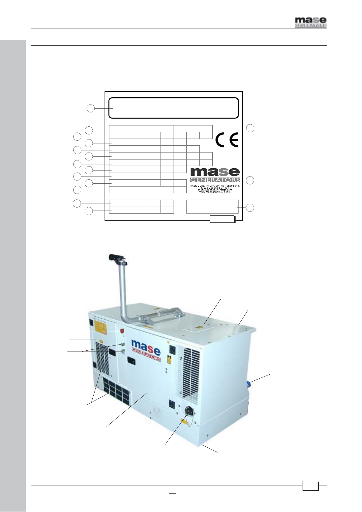
1 Identificazione della macchina .............. 5
1.1 Composizione dei gruppi elettrogeni ........... 5
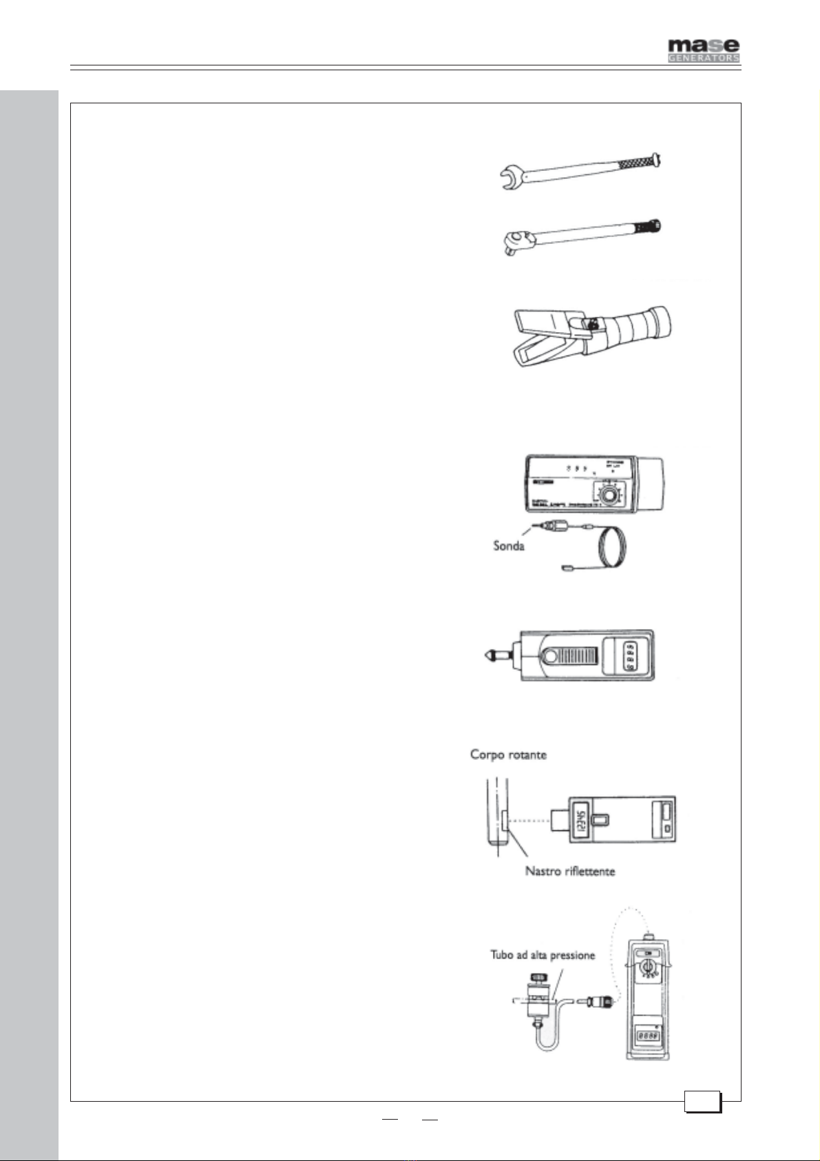
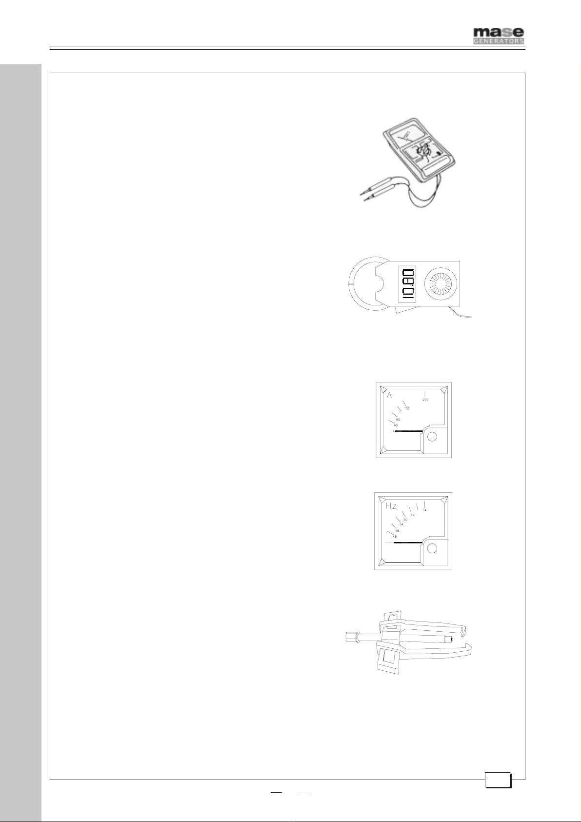
2 TABELLA ATTREZZI .................................. 9
3 ALTERNATORE ........................................ 13
3.1 Statore ...................................................... 15
3.1.1 Avvolgimenti di potenza ............................. 15
3.1.2 Avvolgimenti di eccitazione ....................... 17
3.2 Rotore ....................................................... 19
3.2.1 Avvolgimento di campo eccitatrice ............ 19
3.2.2 Ponte diodi rotante .................................... 21
3.2.3 Varistore ................................................... 21
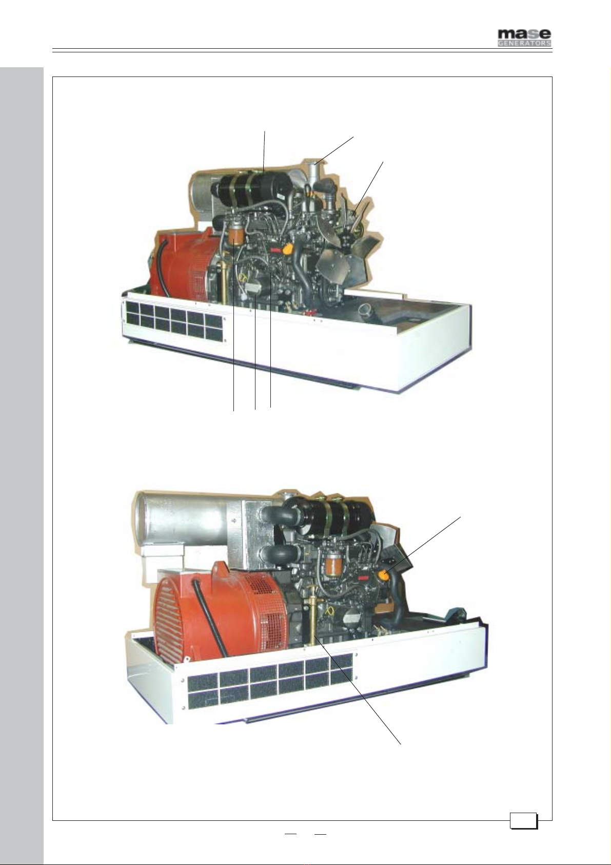
4 MOTORE .................................................. 23
4.1 Caratteristiche tecniche ............................ 23
4.2 Manutenzione ........................................... 26
4.3 Tavola guasti ............................................. 28
4.4 Combustibile ............................................. 33
4.5 Filtro gasolio a cartuccia .......................... 35
4.6 Lubrificazione ............................................ 37
5 SENSORI ................................................. 39
5.1 Valvola termostatica .................................. 39
5.2 Termointerruttore motore a circuito chiuso 41
5.3 Pressostato olio........................................ 43
6 RAFFREDDAMENTO ................................ 45
7 REGOLAZIONI ......................................... 47
7.1 Regolazione dei giri .................................. 47
7.2 Regolazione serrature e maniglie .............. 49
8 IMPIANTO ELETTRICO ........................... 51
8.1 Cruscotto .................................................. 51
8.2 Magnetoidraulico (AC circuit breaker) ....... 53
8.3 Termico linea 12V ..................................... 55
8.4 Cablaggio motore ...................................... 57
8.5 Alternatore carica batteria ......................... 59
8.6 Elettromagnete motore ............................. 61
8.7 Motorino avviamento ................................. 63
8.8 Regolatore di tensione (A.V.R.)................. 65
8.8.1 Funzione dei potenziometri del regolatore 65
8.8.2 Procedura di collaudo su macchina .......... 69
8.9 Batteria ..................................................... 71
9 SMONTAGGIO ......................................... 73
9.1 Rimozione della cassa .............................. 73
9.2 Rimozione alternatore ............................... 83
9.3 Rimozione dellacarcassa alternatore ........ 85
9.4 Rimozione del rotore ................................. 87
RICAMBI SILENT 12
MOTORE .................................................. 89
CASSA ..................................................... 91
PANNELLO COMANDI ............................. 93
SCHEDA ORDINI RICAMBI ....................... 94
SCHEMA ELETTRICO .............................. 95
Index
1 Machine identification ......................... 5
1.1 Generators composition .......................... 5
2 TOOLTABLE .......................................... 9
3 ALTERNATOR ..................................... 13
3.1 Stator .................................................... 15
3.1.1 Power windings ..................................... 15
3.1.2 Excitation windings ............................... 17
3.2 Rotor ..................................................... 19
3.2.1 Excitation field ...................................... 19
3.2.2 Rotor diodes ......................................... 21
3.2.3 Varistor ................................................. 21
4 ENGINE ................................................ 25
4.1 Technical features ................................. 25
4.2 Maintenance ......................................... 27
4.3 Trouble-shooting ................................... 30
4.4 Fuel ...................................................... 33
4.5 Gas-oil filter cartridge ............................ 35
4.6 Lubrication ............................................ 37
5 SENSORS ............................................ 39
5.1 Thermostatic valve ................................ 39
5.2 Closed-circuit engine thermal switch .... 41
5.3 Oil pressure switch ............................... 43
6 SEA WATER COOLING ....................... 45
7 ADJUSTMENTS ................................... 47
7.1 Rpm adjustment ................................... 47
7.2 Lock and handle adjustment ................. 49
8 ELECTRICAL SYSTEM ........................ 51
8.1 Control panel ........................................ 51
8.2 Magnetohydraulic switch (AC circuit breaker) . 53
8.3 12V line thermal switch......................... 55
8.4 Engine wiring ........................................ 57
8.5 Battery charger alternator ..................... 59
8.6 Engine electromagnet ........................... 61
8.7 Starter motor ........................................ 63
8.8 Voltage regulator (A.V.R.)..................... 65
8.8.1 Functions of the regular potentiometers 65
8.8.2 Machine test procedure ........................ 69
8.9 Battery .................................................. 71
9 DISASSEMBLY .................................... 73
9.1 Removing the casing ............................. 73
9.2 Removing the alternator ........................ 83
9.3 Removing the stator casing .................. 85
9.4 Removing the rotor ................................ 87
SILENT 12 SPARE PARTS
ENGINE ................................................ 89
FRAME ................................................. 91
CONTROL PANEL ................................ 93
ORDERS EXCHANGE FILE .................. 94
WIRING DIAGRAM ............................... 95
1 INDICE