Martin maxxyz modules series Manuel utilisateur

MAXXYZ™MODULES
USER MANUAL

Maxxyz Modules User Manual 2
©2009 Martin Professional A/S. Information subject to change without notice. Martin Professional A/S and all
affiliated companies disclaim liability for any injury, damage, direct or indirect loss, consequential or economic
loss or any other loss occasioned by the use of, inability to use or reliance on the information contained in this
manual. The Martin logo, the Martin name and all other trademarks in this document pertaining to services or
products by Martin Professional A/S or its affiliates and subsidiaries are trademarks owned or licensed by
Martin Professional A/S or its affiliates or subsidiaries.
P/N 35000223, Rev. A

Maxxyz Modules User Manual 3
Table of Contents
1. Introduction......................................................................................................... 5
1.1 Technical support .................................................................................... 5
1.2 Safety information.................................................................................... 5
1.3 Connecting to power................................................................................ 6
1.4 Included items.......................................................................................... 6
2. Setup and Assembly........................................................................................... 7
2.1 Single ‘stand-alone’ Maxxyz Module........................................................ 7
2.2 Mounting in a Maxxyz Module Frame...................................................... 7
Installing a module in the lower opening of the Frame ....................... 7
Installing a module in the upper opening of the Frame....................... 9
2.3 Notes ......................................................................................................12
3. Daisy-chaining modules ....................................................................................13
4. Connections and configuration..........................................................................14
4.1 Cerebrum Module connections panel .....................................................14
4.2 Programmer, Submaster, Playback, Button connections panel..............15
4.3 Connections............................................................................................16
4.4 Configuration ..........................................................................................16
4.5 Software..................................................................................................16
4.6 Controls ..................................................................................................16
5. Service ..............................................................................................................17
5.1 Cleaning..................................................................................................17
6. Specifications ....................................................................................................18

Maxxyz Modules User Manual 4

Maxxyz Modules User Manual 5
1. Introduction
Thank you for selecting a product from the Martin Professional™ Maxxyz™ Modules
range.
The Maxxyz Modules are an extension to the Maxxyz™ controller, the Maxxyz
Compact™ controller or the Maxxyz PC™ family.
The Maxxyz Modules concept consists of either one or two modules installed in one
Module Frame.
This manual matches the functionality in Version 2.6 of the Maxxyz software. For the
latest firmware and software updates, documentation and other information about
this controller, see www.maxxyz.com
1.1 Technical support
For a complete list of Technical Support phone numbers, see the Martin website at
http://www.martin.com/service/hotline.asp
1.2 Safety information
This product is for professional use only. It is not for household use. It presents risks
of lethal or severe injury due to electric shock. Read this user manual before
powering or installing the Modules, follow the safety precautions listed below and
observe all warnings in this manual and printed on the product
If you have questions about how to operate the product safely, please contact your
Martin supplier or call the Martin 24-hour service hotline on +45 8740 0000, or in the
USA on 1-888-tech-180.
•Connect the product electrically to ground (earth).
•Use only a source of AC power that complies with local building and electrical
codes and has both overload and ground-fault protection.
•Replace fuses with ones of the same type and rating only. Never attempt to
bypass a fuse.
•Disconnect the product from power immediately if the power cable or any
cover or component is wet or not in perfect condition. Do not reconnect to
power until the damaged item has been repaired or replaced.
•Do not expose the product to rain or moisture.
•Allow free unobstructed airflow to the front and the back of the product.
•Do not use the product if the ambient temperature exceeds 40°C (104° F)
•Refer any service operation not described in this manual to a qualified
technician.
•Do not modify the product or install other than genuine Martin parts.
Maxxyz Modules User Manual 6
•Before transportation, secure modules in place in a frame with the supplied
screws.
1.3 Connecting to power
Maxxyz Modules automatically adapt to AC mains power at 100-240 V nominal,
50/60 Hz. Do not connect them to power outside this range.
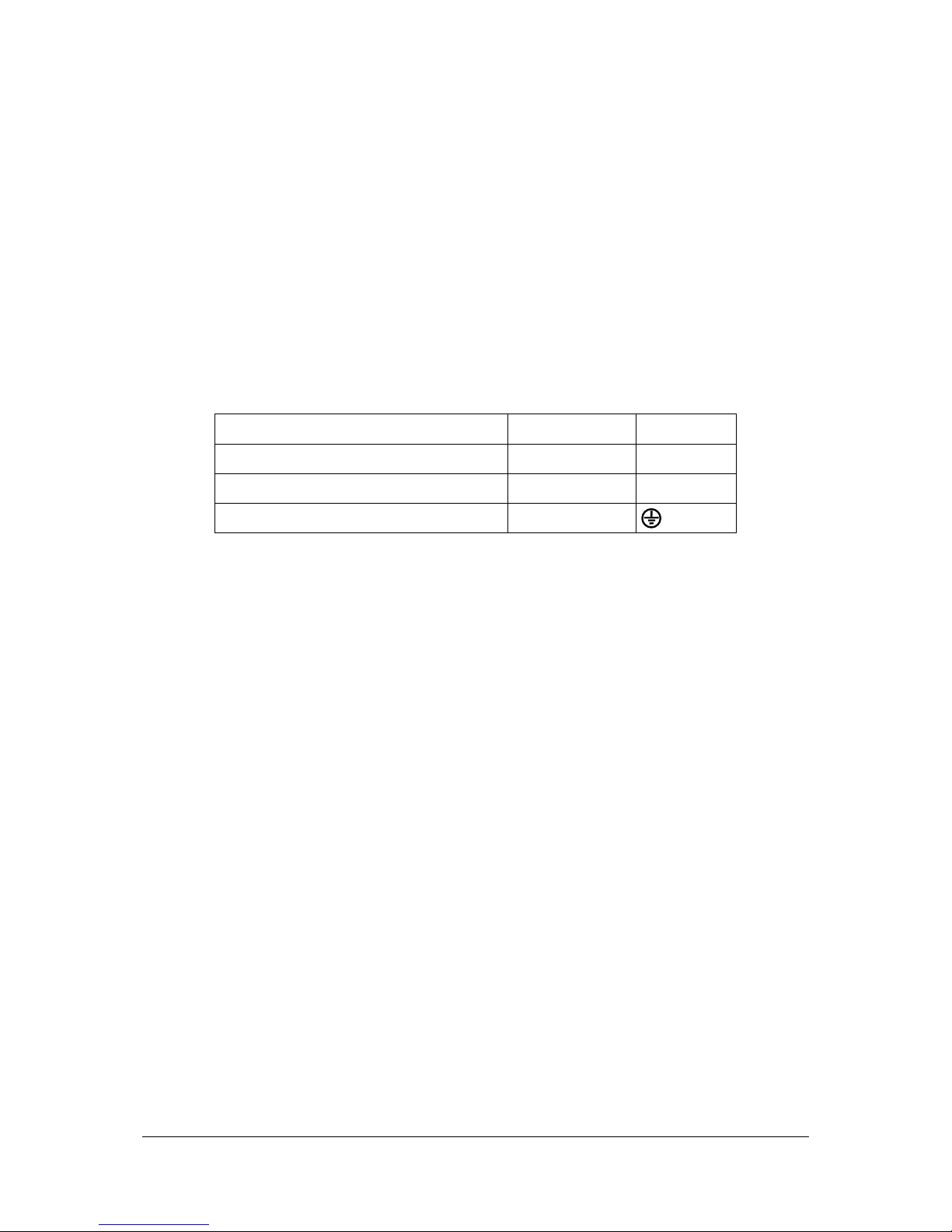
You may need to install a cord cap that fits your supply on the power cable. A 3-
prong grounding-type plug must be installed following the plug manufacturer’s
instructions. The table below shows some possible pin identification schemes; if the
pins are not clearly identified, or if you have any doubts about proper installation,
consult a qualified electrician.
Wire color (standard EU code) Pin Symbol
brown live
L
blue neutral
N
yellow/green ground
1.4 Included items
Each Maxxyz Module, part numbers 90732140 (Cerebrum), 90732150
(Programmer), 90732160 (Button), 90732170 (Submaster) and 90732180
(Playback), contains the following items:
•Maxxyz Module
•Two 2 AT fuses, installed
•IEC Power cable (part number 11501012)
•Ethercon Network cable (part number 11840144)
•USB cable (part number 11840066)
•User manual (part number 35000223)
Each Module Frame, part number 90732120 (shipped in flightcase) and 90732130
(shipped in cardboard box) contains the following items:
•Module Frame with attached Ethercon Power interconnect cables and
desklight cable
•Desk lamp (built in)
•Blind cover plate (installed)
•Dust cover

Maxxyz Modules User Manual 7
2. Setup and Assembly
There are two different methods of setting up the Maxxyz Modules: one for “stand-
alone” use and one for mounting in a Maxxyz Module Frame.
2.1 Single ‘stand-alone’ Maxxyz Module
Each module is shipped with protective foam attached to each side. This foam
supports the faceplate and prevents cosmetic damage to the module. Apart from
connection to the controller, the module is “ready to use” as soon as it is removed
from its packaging.
2.2 Mounting in a Maxxyz Module Frame
Installing a module in the lower opening of the Frame
1. Remove the module(s) and the module frame from their packing material.
2. Use a 3 mm Allen wrench to remove the two screws that attach the side strips to
each side of the module opening in the frame.

Maxxyz Modules User Manual 8
3. The module can now be placed in the lower opening. Put the side strips back on
each side of the module and fasten them in place with their screws.
Important! The Cerebrum Module only fits in the upper opening of the
Maxxyz Module Frame.
4. Connect the Power interconnect cable to the MAINS IN connector, or, if only one
module is used, connect the IEC Power cable (part number 11501012) to the
MAINS IN connector.

Maxxyz Modules User Manual 9
5. Connect the EtherCon interconnect cable to the WING IN connector, or, if only
one module is used, connect the EtherCon Network cable (part number
11840144) to the WING IN connector.
6. Connect the Lamp bayonet plug to the “LAMP” connector. This will connect the
top illumination to the module.
Installing a module in the upper opening of the Frame
Cerebrum module
1. Use a 3 mm Allen wrench to remove the four screws that attach the blind cover
plate (if installed) to the frame.
2. The Cerebrum Module can now be placed into the top opening. Put the side strips
back on each side of the frame and fasten them in place with their screws.

Maxxyz Modules User Manual 10
3. Connect the Power interconnect cable to the MAINS OUT connector.
4. Connect the EtherCon Network cable (part number 11840144) to the WING OUT
connector.
5. Connect the IEC Power cable (part number 11501012) to the MAINS IN
connector.
Important! The Cerebrum Module is a controller module and must not
be connected to a Maxxyz controller, a Maxxyz Compact controller, a
Maxxyz PC or another Cerebrum using the WING OUT outputs. The
WING OUT outputs must only used to connect non-controller modules
(Programmer, Button, Submaster and Playback Modules) to the
Cerebrum.
Table des matières
Autres manuels Martin Contrôleurs

Martin
Martin M6 Series Manuel utilisateur

Martin
Martin M6 Series Manuel utilisateur

Martin
Martin P3-100 Manuel utilisateur

Martin
Martin Maxxyz Manuel utilisateur

Martin
Martin M2GO HD Manuel utilisateur

Martin
Martin M6 Series Manuel utilisateur

Martin
Martin DMX 8 Zone Manuel utilisateur

Martin
Martin DMX 8 Zone Manuel utilisateur

Martin
Martin DMX Controller 2518 Manuel utilisateur

Martin
Martin M2GO Manuel utilisateur


