MARSS Solar Defender ALM-6814 Instructions de montage
ALM-6814/6815
INSTALLATION AND
PROGRAMMING
MANUAL
Installation and Programming Manual V1.2 1

MARSS Solar Defender ® Sy tem
This essential guide provides specific installation and configuration of devices ALM-6 14/6 15
in stand alone mode. For operation with RS-4 5 bus, see the manual installation and
configuration of the ALM-6 00.
Important: The MARSS Srl re erve the right to change the manual without prior
notice, or any part thereof, in order to improve the quality and performance of the
product and the in tallation of the y tem it elf.
Vi it the ite www.mar .eu regularly for update of MARSS product
Installation and Programming Manual V1.2 2

Table of Content
SAFETY PRECAUTIONS....................................................................................................3
FEATURES OF DEVICES...................................................................................................4
EXPLODED VIEW............................................................................................................5
Concentrator module for fiber-optic Solar Defender (model ALM-6 14/6 15).........................6
Description of the concentrator module.............................................................................7
Bus Input A B C D terminal block.................................................................................
Bus Output A B C D terminal block...............................................................................
Fuse F4.....................................................................................................................9
Tamper terminal block.................................................................................................9
Fiber Optic TX and RX...............................................................................................10
Cutting and torsion fiber signalling relay......................................................................11
Reset button and External Reset terminal block............................................................12
Open Collector OC1, OC2 and OCF outputs..................................................................12
Using the OCF Open Collector output......................................................................13
Use first mode..................................................................................................13
Use second mode.............................................................................................14
Use third mode.................................................................................................15
Auxiliary power supply X7 terminal block.....................................................................16
Fuse F1...................................................................................................................16
JP6 e JP3 Jumpers....................................................................................................16
Dip-switch SW2 Function...........................................................................................17
Loop fiber adjustment ALM-6 15 and ALM-6 14...............................................................1
Fiber loop calibration.................................................................................................19
Primary calibration................................................................................................19
Fine calibration.....................................................................................................19
Dip-switch S3 Address...............................................................................................22
Addressing operation................................................................................................23
Jumper JP3..............................................................................................................24
Seven Segments Display...........................................................................................24
Wiring inside the container ...........................................................................................24
Cable gland on the container .....................................................................................25
Connection and passing of the optical fiber .................................................................26
Minimum curvature of the fiber..............................................................................2
Power Supply features...................................................................................................2
Terminal blocks on power supply module.....................................................................29
Autonomy of operation with battery backup.....................................................................30
TECHNICAL SPECIFICATIONS.........................................................................................31
Note:..........................................................................................................................32
Declaration of Confirmity...............................................................................................35
Installation and Programming Manual V1.2 3
SAFETY PRECAUTIONS
The installation of the product must be performed by qualified personnel in accordance with
local laws and regulations on safety.
In agreement with the European Directive 2004/10 /EC (EMC), the product must be installed
using equipment, cables and accessories that allow it to meet the requirements of the Directive
for fixed installations.
The product must be connected to the mains supply by following the instructions in this
manual.
Keep physically separated extra low voltage wires, including the battery, the wire low voltage
(230Vac).
IMPORTANT
Only trained and authorized personnel can service the product, with the aim of making the
connections described in this manual. In case of failure do not attempt to repair the product or
the warranty will no longer be valid.
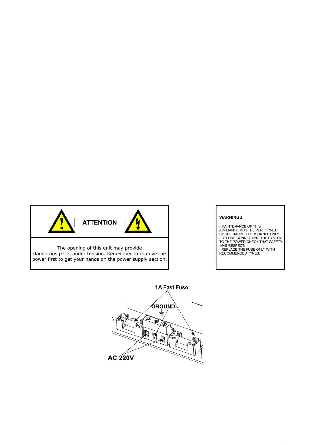
The opening of this unit may provide dangerous parts under tension. Remember to disconnect
the power before you get your hands on the power supply section.
It is recommended to periodically verify the proper functioning of the alarm system, however,
a reliable electronic alarm system will not prevent theft, tampering, fire, etc., but merely
reduce the risk that such situations occur.
ACCORDANCE WITH THE EUROPEAN DIRECTIVES
The product meets the essential requirements of European Directive 2004/10 /EC
(Electromagnetic Compatibility Directive - EMC) and is therefore consistent with the
harmonized standards EN 50130-4, EN 61000-6-3.
To connect to the 230V, use cables with greater than 0.5 mm and with an extra
jacket to ensure greater protection.
Installation and Programming Manual V1.2 4
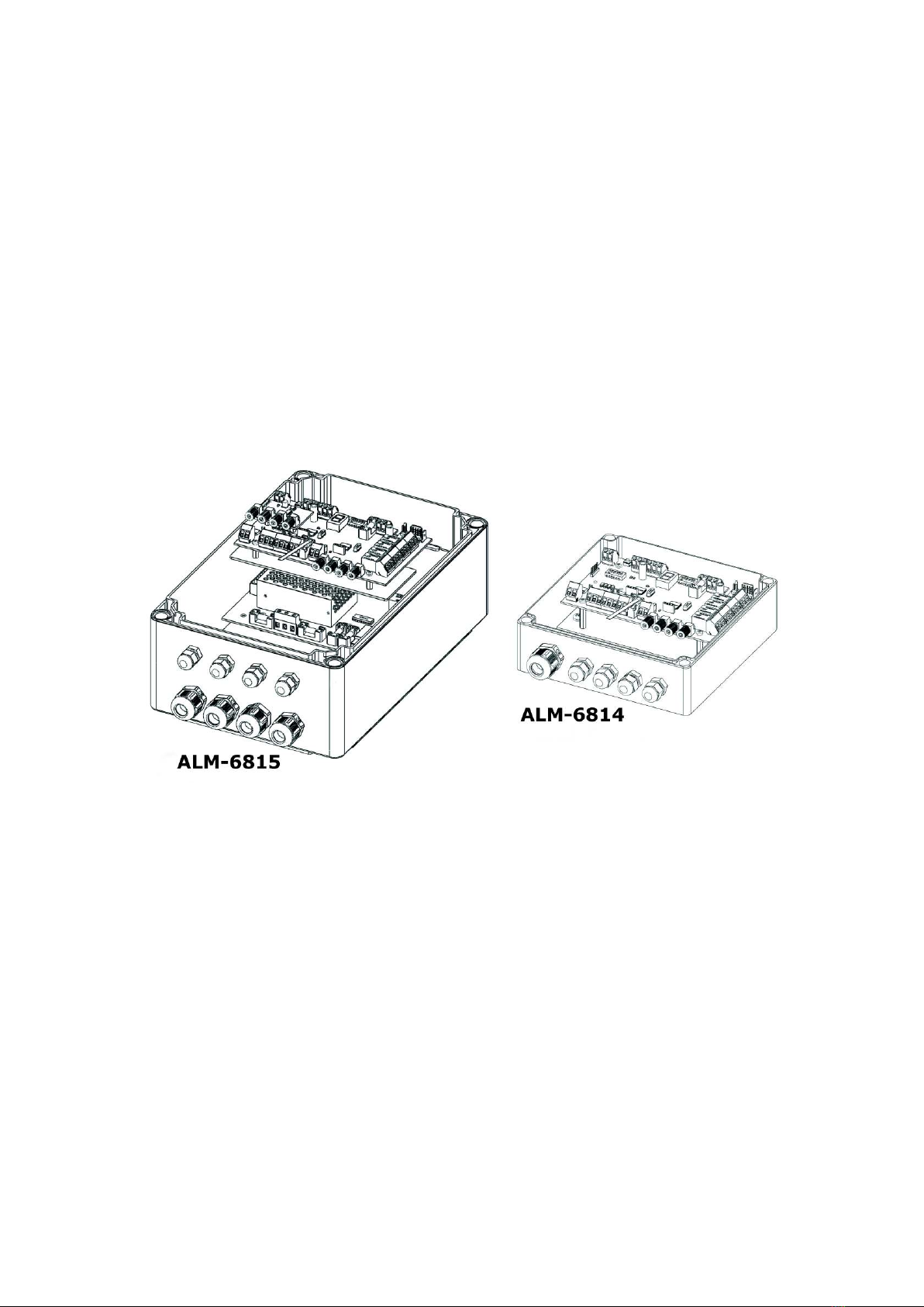
FEATURES OF DEVICES
In this part of the manual lists the major hardware features and functions of the plastic optical
fiber devices ALM-6 15, ALM6 14 and fiber optic connection module to the RS-4 5 bus.
ALM6 15 is an antitheft device, fiber optic plastic double loop. It functions is based on cut and
torsion control of the optical fiber. It can work both in stand-alone (autonomous), using the
relay and open collector outputs for the onboard alarm cut or torsion fibers, in either RS-4 5
bus to send these reports directly to the central management unit ALM-6 00. Its housed in a
200x300x132 container, equipped with a supervised power supply with main supply and status
battery control. In BUS RS-4 5 mode the control unit ALM-6 00 receives alarms both cut and
torsion fiber, both the main supply 230Vac presence and status of internal battery of each
device connected to the system bus.
ALM6 14 has within the same circuit board with features identical to those of the ALM6 15,
but without the power module 230Vac. For this model, the device operates at 12V and is
housed in a 175x175x75 container.
ALM-6 15 and ALM-6 14 have the following characteristics:
1. Double-loop fiber, with 200 meters per loop, with cut and torsion management;
2. Torsion adjustment system for each loopmanagement;
3. Four relay outputs for reporting cut and torsion for each loopmanagement;
4. Open Collector output signal blocking operation of the concentratormanagement;
5. Dual mode, stand-alone, and RS-4 5 bus selectable via dip switches;
6. Seven-segment LED display for viewing of alarms and calibration of the device.
Installation and Programming Manual V1.2 5
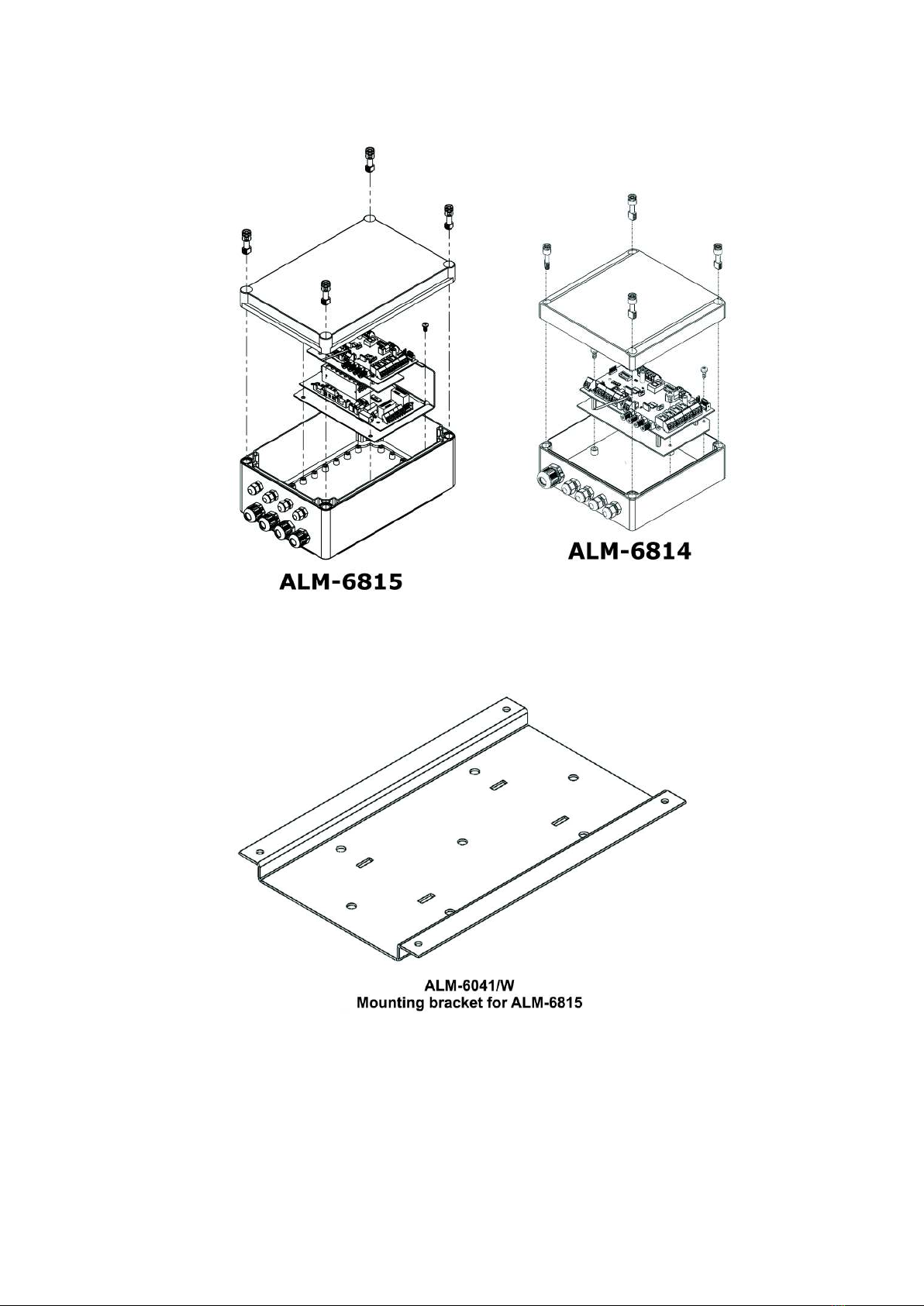
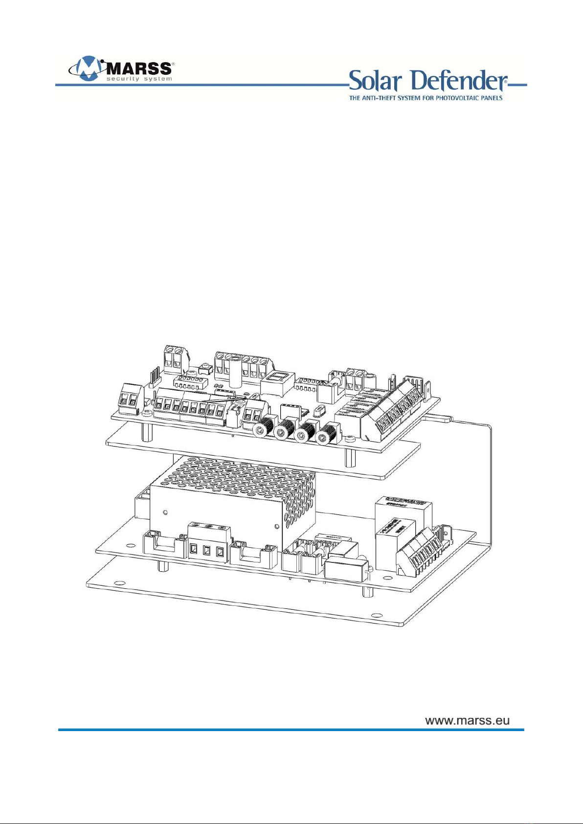
EXPLODED VIEW
Installation and Programming Manual V1.2 6
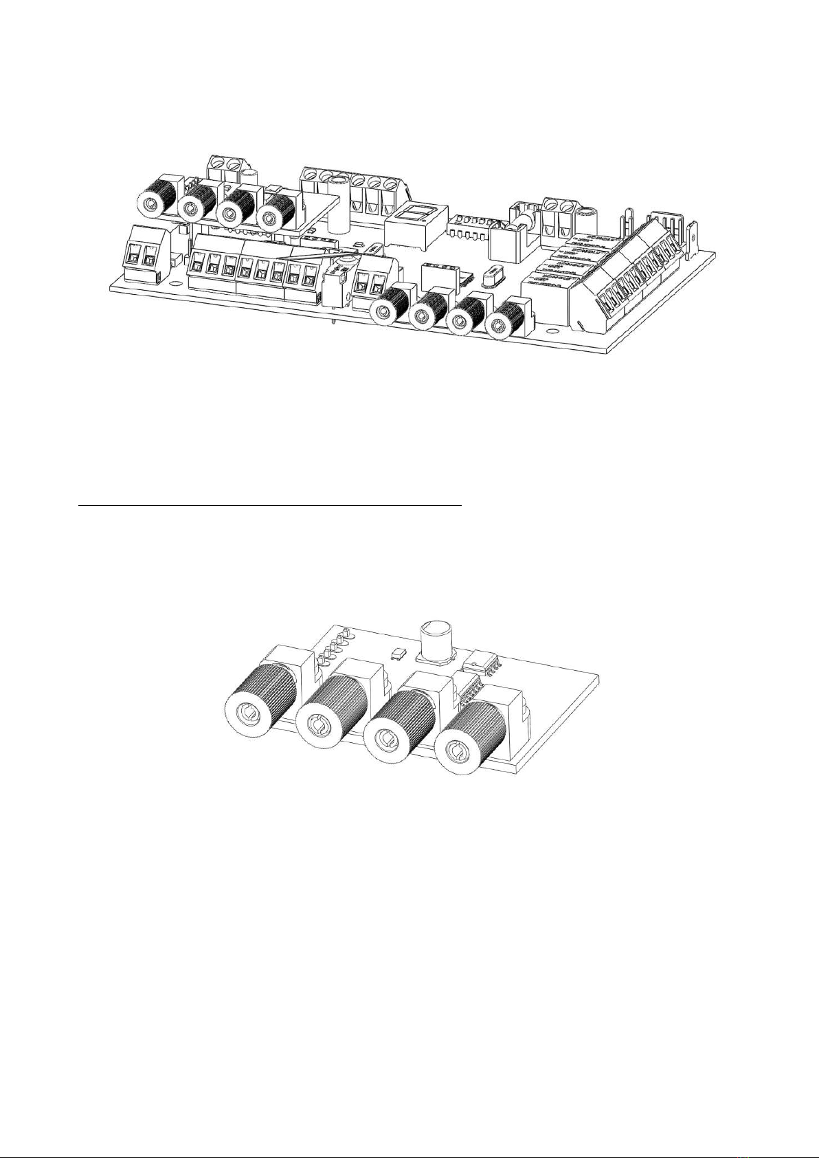
Concentrator module for fiber-optic Solar Defender (model ALM-6814/6815)
The concentrator module ALM-6 14/6 15 manages 2 lines plastic optical fiber (POF - Plastic
Optical Fiber) from 200 meters by 2 loops. It can work in stand-alone or centralized mode on
RS-4 5 bus.
ALM-6 15: Fiber optic concentrator, with supervised power supply module.
ALM-6 14: Fiber optic concentrator without supervised power module.
This manual only refers to the stand-alone operation. For the operation on BUS refer to the
installation and programming manual of the ALM-6 00.
Modulo convertitore BUS-Fibra (optional)
The concentrator modules are designed to interface the RS-4 5 bus using a plastic optical fiber
converter module.
Note: The drive-BUS fiber will soon be available.
Installation and Programming Manual V1.2 7
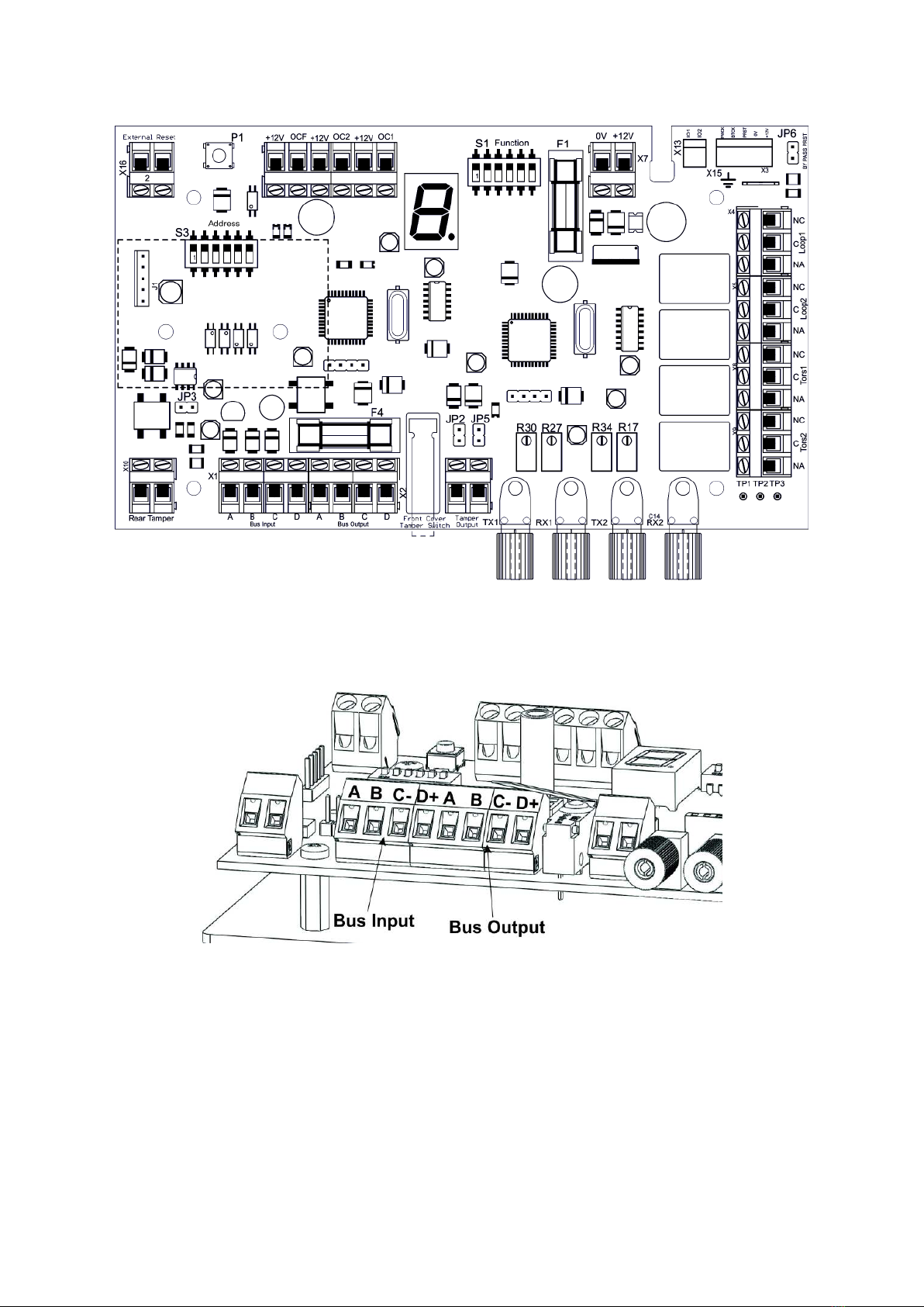
De cription of the concentrator module
Bu Input A B C D terminal block
Terminal block for connecting the RS-4 5 bus from the central unit (For use on bus mode. In
stand-alone is not used)
A Data Bus "A" (green if you use the cable MARSS ALM-6021)
B Data Bus "B" (yellow if you use the cable MARSS ALM-6021)
C Negative power supply from central unit ALM-6 00 (black if you use the cable MARSS ALM-
6022 and any other cables)
D +24V Positive power supply from central unit ALM-6 00 (red if you use the cable MARSS
ALM-6022)
Installation and Programming Manual V1.2
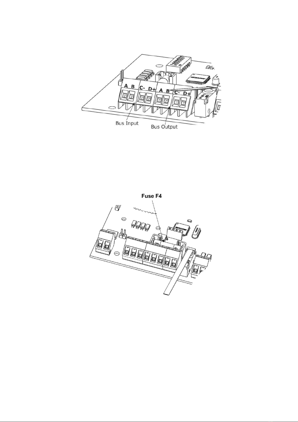
Bu Output A B C D terminal block
Terminal block for connecting the RS-4 5 bus to the next concentrator module.
A Data Bus "A" (green if you use the cable MARSS ALM-6021)
B Data Bus "B" (yellow if you use the cable MARSS ALM-6021)
C Negative power supply to the next concentrator module (black if you use the cable MARSS
ALM-6022 and any other cables)
D +24V Positive power supply to the next concentrator module (red if you use the cable
MARSS ALM-6022)
Fu e F4
Fast Fuse 1A power protection from the bus RS-4 5.
Installation and Programming Manual V1.2 9
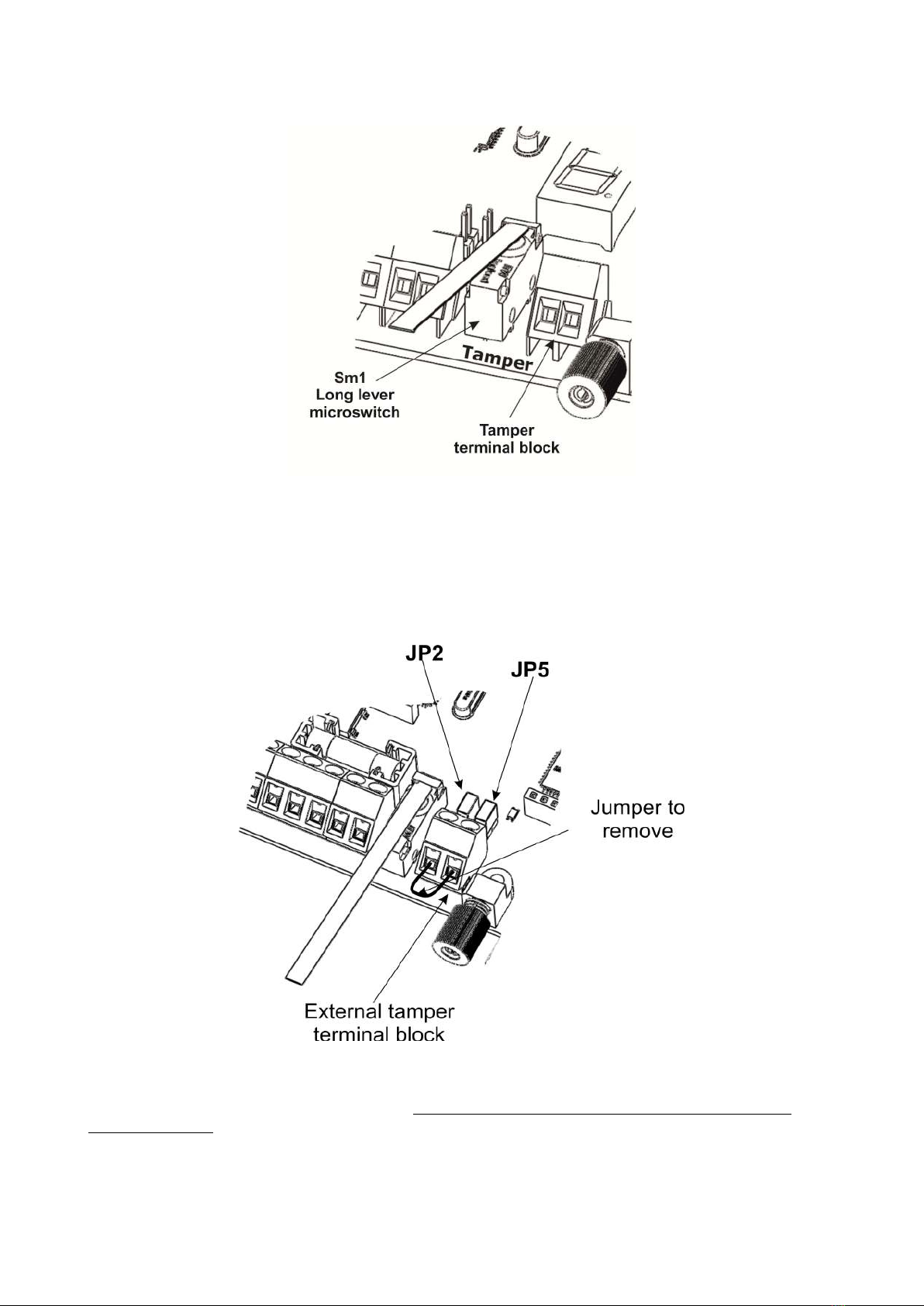
Tamper terminal block
The concentrator module has an internal long lever microswitch for tamper protection of the
container. If you use mode of operation on bus, the device will indicate tampering with the
control unit via BUS.
In standalone mode, you can use the terminal block for connection to any burglar alarm or
signaling device (telephone dialer, radio, etc. ..). In this case we must remove the jumpers JP2
and JP5.
Note: Both in the operation on bu , both in tand-alone, after the in tallation and
te ting of the concentrator, we mu t remove the jumper on the external tamper
terminal block. Leaving the jumper connected to the terminal, the tamper will remain
inactive.
Installation and Programming Manual V1.2 10
Ce manuel convient aux modèles suivants
1
Table des matières


