Mars Azure Digi-Motor Manuel utilisateur

Digi-Motor®nstallation Guide
MARS No. 10860/10861
®
marsdelivers.com

Digi-Motor®nstallation Guide
2
®
Ta le of Contents
Product Description.........................................................................................................3
Safety..............................................................................................................................3
Mounting & Configuring ..................................................................................................4
Connecting Power Wires .............................................................................................5-7
Connecting & Auto Sizing for PSC Applications .............................................................6
Connecting & Auto Sizing for X-13 Applications ............................................................7
Adjusting Motor Speeds..................................................................................................8
Operating in Constant Fan Mode..............................................................................9, 10
Troubleshooting ............................................................................................................10
Typical Connections, PSC & X-13 Applications ............................................................11
Please read the entire instruction manual efore starting the installation.
Digi-Motor®
For technical assistance with your
Azure®Digi-Motor®, call the MARS
technical support hotline:
800-678-9888
M-F 8 am – 5 pm EST.
©2019 MOTORS & ARMATURES, Inc.
All rights reserved. This catalog may not be reproduced in whole or in part in any form without written permission from Motors & Armatures, Inc.
MAR is a registered trademark of Motors & Armatures, Inc. MAR part numbers are trademarks of Motors & Armatures, Inc.

Digi-Motor®nstallation Guide
3
®
www.marsdelivers-contractors.com
Product Description
The Azure®Digi-Motor®from MARS is a high efficiency variable speed direct drive blower motor for a multitude of
applications. Azure®is a replacement for both standard PSC and Genteq X-13 motors. Two motors
cover ratings from 1/5 HP to 1 HP at 115V or 230V and CW or CCW.
Azure®features an auto sizing learn mode. n start-up learn mode, Azure®runs for approximately 2 minutes measuring
the external static pressure of the system application. Azure®then assigns torque values to each of its speed taps self-
programming itself to the correct horsepower for the application.
f none of the four speeds provides perfect airflow for the application or if duplicate speeds are desired on 2 or more
taps, an optional hand held programmer (MARS No. 08502) can be used. The programmer connects to Azure®and
displays the percentage of torque applied to the speed tap being energized. The percentage (motor speed) can then
be increased or decreased and permanently set with the programmer. This tool overrides the motor torques
established in the auto sizing mode.
Unlike other electronically commutated motors, an outboard surge protector is included within Azure’s®wire harness.
This is a replaceable device (MARS No. 08593).
• Outboard replaceable surge protector
• Adjustable speeds (with optional MARS No. 08502)
• 625 RPM constant fan speed tap
• Reversible rotation, dual voltage
• High efficiency 85%
Use this motor only in applications for which it
was designed.
• The Azure®Digi-Motor®is intended for use in
direct drive centrifugal blower applications.
• The Azure®Digi-Motor®is designed for
continuous, air-over duty and must be
mounted in the air stream of an air-moving
device to ensure proper cooling of the motor.
• Do not use this motor in locations containing
explosive vapors.
• The ambient operating temperature range is
-4˚F (-20˚C) to 131˚F (55˚C).
• Only trained and qualified HVAC professionals
should install this motor.
• Before disconnecting or connecting the HVAC
blower motor, ensure that power is shut off to
the system. Failure to do so may result in
system damage or personnel injury.
• Do not operate the motor without a load
(blower wheel).
• Always ensure the voltage jumper on the
motor is set to match the voltage of the
system.
Safety
To reduce the risk of electrical shock, do not separate motor and control unit. The control unit has no serviceable
parts.
To reduce the risk of electrical shock or fire, do not expose the motor to rain or moisture.
• Multi-horsepower, direct drive
• Constant torque
• 4 Speeds
• Belly band mount
• No capacitor required
WARNING! WARNING!
WARNING - SHOCK HAZARD!

Digi-Motor®nstallation Guide
4
®
www.marsdelivers-contractors.com
To prevent electric shock, personal injury, or death, turn off the electric power at the disconnect or main service
panel prior to making any electrical connections.
The installation of this motor must comply with all local codes and the NEC, article 430.
1) nstall the Azure®Digi-Motor®into the blower housing using a
high quality bellyband. Be careful not to block the oval
ventilation holes nearest the end bell (shown in the ima e
below).
• MARS No. 08025 (10” bolt pattern)
• MARS No. 08026 (11” bolt pattern)
• MARS No. 08027 (13” bolt pattern)
Orient the power harness downward (between the 4 o’clock
and 8 o’clock positions). This will help prevent moisture from
penetrating the control module on the motor. Refer to mage 1.
2) Secure the blower wheel to the motor shaft ensuring the wheel
is centered within the housing. Image 1: Motor Orientation
WARNING!
The Azure®Digi-Motor®must e securely mounted to minimize noise and vi ration.
A high quality elly and with olts is the desired means for mounting Azure®.
Ensure the Azure®Digi-Motor®is an equivalent (in terms of HP rating) for the motor eing replaced.
Azure®MARS No. 10860: 1/5 HP – 1/2 HP
Azure®MARS No. 10861: 1/2 HP – 1 HP
NOTICE
1) Disconnect main power to the HVAC system.
2) Note the motor voltage, horsepower, and rotation of the motor being replaced.
3) Disconnect the existing motor wire harness (from the control board), neutral, ground, and capacitor.
4) Remove the blower assembly and discard the capacitor.
5) Remove the old motor and mounting bracket.
Removing The Old Motor
Configuring The Azure®Digi-Motor®

Digi-Motor®nstallation Guide
5
®
www.marsdelivers-contractors.com
3) Connect the surge protector into the wire harness. Refer to image 7.
Set the motor voltage to match the application using the RED
voltage wire pigtail leads: Refer to image 2.
4) Set the motor rotation to match the application using the WH TE
rotation wire pigtail leads: Refer to image 3.
CWLE: Connect the WH TE rotation leads together
(closed circuit).
CCWLE: Leave the WH TE leads disconnected
(open circuit).
5) Set the motor mode of operation (PSC or X-13) to match the
application using the BLUE mode of operation pigtail leads:
Refer to image 4.
PSC: Connect the BLUE mode of operation leads together
(closed circuit).
X-13: Leave the BLUE mode of operation leads disconnected
(open circuit).
X-13: nstall the X-13 PC board into the speed tap wire harness
by unplugging the connector and inserting the X-13 PC
board. Refer to image 5 & 6.
X-13: Unplug and discard the WH TE and GREEN/YELLOW
Azure®power wire harness. (The factory X-13 power
harness will replace this harness)
6) nstall the blower assembly back into the HVAC equipment.
Configuration Leads
Image 4: Mode of Operation
Image 5: X-13 C Board
Image 6: X-13 C Board Location
Image 7: Surge rotector
Image 3: Rotation
Image 2: Voltage
Configuring The Azure®Digi-Motor® cont.

Digi-Motor®nstallation Guide
6
®
www.marsdelivers-contractors.com
Image 7: Auto Size Harness
This motor must initially e put through a rief programming mode. During this procedure,
the Azure®Digi-Motor®will run for approximately 2 minutes while it measures the external
static pressure of the application. This process programs the motor to a horsepower value appropriate for the
application and esta lishes proper torque values on each of the speed taps. This is necessary for oth PSC and
X-13 applications. The auto sizing process can performed as many times as desired. Each auto sizing event
overrides the previous event.
NOTICE
Connecting & Auto Sizing For PSC Applications
WARNING!
To prevent electric shock, personal injury, or death, turn off the electric power at the disconnect or main service
panel prior to making any electrical connections.
1) Turn off the system thermostat. Make certain all supply registers,
grilles, and zones are open and unobstructed. Make certain the air
filter is clean. This is very important for accurate auto sizing and best
performance of Azure
®
.
2) With the power removed from the HVAC system, make the following
connections: Refer to wiring diagram A.
• GREEN/YELLOW (Ground) lead to system ground
• WH TE (N/L2) lead to Neutral or L2 (230V applications)
• RED (Tap 5 High) lead to L1.
Note: This is a temporary connection for auto sizing the motor.
• BROWN & WH TE (24V & Common) harness to
24V transformer
Note: This is a temporary connection for auto sizing the motor.
Refer to image 7
3) Close the blower housing door. Carefully apply power to the HVAC
system. The motor will run for approximately 2 minutes and then stop.
Note: f power is left on, the motor will restart after 30 seconds and
run at speed tap 5.
IM ORTANT: THE ROCESS IS NOT COM LETE UNTIL THE
MOTOR COMES TO A COM LETE STO . DO NOT REMOVE
OWER UNTIL THE MOTOR STO S. IF THE MOTOR DOES NOT
STO , SEE TROUBLESHOOTING.
4) Remove power to the HVAC system.
5) Disconnect the BROWN & WH TE harness and RED speed tap 5.
6) Connect the 115V motor speed taps (select from High, Medium High,
Medium, Medium Low, or Low) to the HVAC system control board;
these connections match the connections of the PSC motor being
replaced. DO NOT CONNECT ANY OF THE SPEED TAPS (1-5) TO
NEUTRAL. See diagram on p.11. Carefully tie off any unused taps.
Note: f low speed (625 RPM) constant fan is desired, proceed to
‘Setting The 625 RPM Constant Fan Feature’.
7) Test complete system operation and confirm proper airflow.
Wiring Diagram A: Azure®Harness Connections for
SC Applications
Ground Neutral
L2
Tap 1
Low
625 RPM
Tap 2
Med Low
Tap 3
Med
Tap 4
Med High
Tap 5
High

Digi-Motor®nstallation Guide
7
®
www.marsdelivers-contractors.com
This motor must initially e put through a rief programming mode. During this procedure,
the Azure®Digi-Motor®will run for approximately 2 minutes while it measures the external
static pressure of the application. This process programs the motor to a horsepower value appropriate for the
application and esta lishes proper torque values on each of the speed taps. This is necessary for oth PSC and
X-13 applications. The auto sizing process can performed as many times as desired. Each auto sizing event
overrides the previous event.
NOTICE
WARNING!
To prevent electric shock, personal injury, or death, turn off the electric power at the disconnect or
main service panel prior to making any electrical connections.
1) Turn off the system thermostat. Make certain all supply registers,
grilles, and zones are open and unobstructed. Make certain the air
filter is clean. This is very important for accurate auto sizing and best
performance of Azure
®
.
2) With the power removed from the HVAC system, make the following
connections: Refer to wiring diagram B.
• HVAC system power harness to the Azure
®
power harness
(24V Common, Line, Ground, Neutral/L2)
• BROWN & WH TE (24V & Common) harness to 24V
transformer Note: This is a temporary connection for auto
sizing the motor.
Refer to image 7
3) Close the blower housing door. Carefully apply power to the HVAC
system. The motor will run for approximately 2 minutes and then stop.
IM ORTANT: THE ROCESS IS NOT COM LETE UNTIL THE
MOTOR COMES TO A COM LETE STO . DO NOT REMOVE
OWER UNTIL THE MOTOR STO S. IF THE MOTOR DOES NOT
STO , SEE TROUBLESHOOTING.
4) Remove power to the HVAC system.
5) Disconnect the BROWN & WH TE harness.
6) Connect the 24V speed taps to the thermostat where the original X-13
was connected. Select from High, Medium High, Medium, Medium
Low, or Low. See diagram on p.11. Carefully tie off any unused tap.
7) Test complete system operation and confirm proper airflow.
Connecting & Auto Sizing For X-13 Applications
Wiring Diagram B: Azure®Harness Connections for
X-13 Applications
24V
Common L1 Ground Neutral
L2
Tap 1
Low
625 RPM
Tap 2
Med Low
Tap 3
Med
Tap 4
Med High
Tap 5
High
Image 7: Auto Size Harness

Electric Shock Hazard. Motor must be properly grounded.
Checking System Operation
Verify that correct airflow is present in all modes of operation. Temperature rise measurements in all modes must
conform to the specifications provided by the original equipment manufacturer. f they do not, proceed to the
ADJUST NG MOTOR SPEEDS section.
Adjusting Motor Speeds
The Azure®motor offers 4 speed taps for Heat/Cool modes and a 625 RPM low speed tap for constant fan use. f the
motor being replaced by Azure®used high (Y) and medium (W) speeds, then high and medium speeds on Azure®
should be a starting point for establishing correct airflow.
Tap 1 Orange: Low Speed (625 RPM)
Tap 2 White or Purple: Med Low Speed
Tap 3 Gray: Med Speed
Tap 4 Yellow: Med High Speed
Tap 5 Red: High Speed
n the event the perfect CFM for the application cannot be obtained, the optional hand held programmer (MARS No.
08502) can be used to adjust the blower speed of any of the 4 motor speed taps (625 RPM tap is fixed and cannot be
adjusted). This tool is useful for:
• Establishing necessary blower speeds in multi-stage / multi speed systems where 4 speed taps are required
• Adjusting CFM in high altitude applications
• Adjusting CFM in high humidity applications
• Providing a digital readout of the percentage of maximum speed being delivered on the tap being energized
WARNING!
Digi-Motor®nstallation Guide
8
®
www.marsdelivers-contractors.com
Once installed, briefly test the motor operation in all system modes: Fan On, Heat, and Cool. Make certain the
blower is operating in the correct direction.
t is normal for the motor to experience a short delay (even a rock back and forth) before beginning operation and
ramping up to full Heat/Cool speed. n PSC mode, the ramp up to speed should be approximately 5 – 10 seconds.
n X-13 mode, the ramp up to speed should be approximately 30 – 45 seconds depending the load.
Digi-Motor®nstallation Guide
9
®
www.marsdelivers-contractors.com
The Azure®Digi-Motor®provides a fixed 625 RPM low speed tap designed for constant fan use. The motor will
operate at 625 RPM whenever this speed tap is energized independently of the other speed taps. f another speed
tap is energized simultaneously with this speed tap, the motor will run at the higher speed.
NOTE: This speed tap CANNOT be adjusted with the hand held programmer.
Continuous fan operation can be achieved in a variety of
ways.
f the system HVAC control board provides a discrete fan
output connection labeled FAN:
• Connect the orange speed tap 1 to this terminal.
Constant fan operation will be controlled by the
user from the thermostat.
f the HVAC system control board DOES NOT provide a
discrete fan output (connection labeled FAN), then:
• Connect the orange speed tap 1 to a line voltage
source AFTER the door interlock switch. NOTE:
DO NOT MAKE TH S CONNECT ON F Azure®S
OPERAT NG N X-13 MODE (24V CONTROL).
Constant fan operation will remain on as long as
power is supplied to the HVAC system. When a
call for Heat/Cool occurs, Azure®will run at the
selected speed tap and then return to 625 RPM
when the call is satisfied.
Or
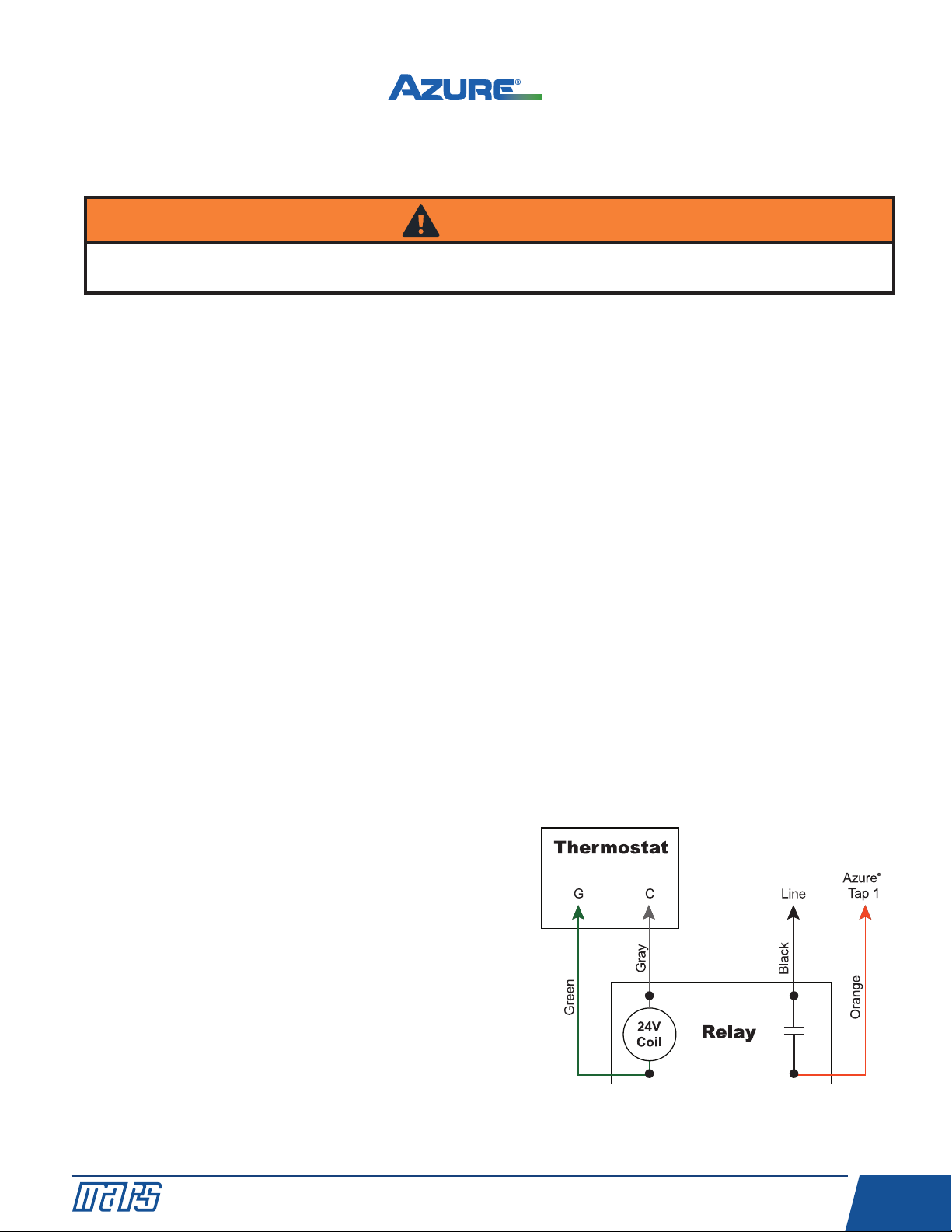
• nstall the optional constant fan relay kit (MARS
No. 08595). The kit consists of a relay and the
necessary pre-cut & terminated wires. The relay is
energized by the 24V signal from G on the
thermostat and sends a line voltage signal to the
orange speed tap 1. Constant fan operation will be
controlled by the user from the thermostat. Refer to
wiring diagram C.
NOTE:
1) Remove G wire between the thermostat and
HVAC system.
2) Some systems energize G and Y for high fan
speed; in this instance jumper G to Y on the
thermostat board.
WARNING!
When operating Azure®in X-13 mode, DO NOT connect the low speed 625 RPM speed tap 1 to a line voltage
source as described below. MOTOR DAMAGE W LL OCCUR. X-13 speed taps are 24V, ONLY.
Operating The System In Constant Fan Mode - Excluding
X-13 Applications
Wiring Diagram C: Constant Fan Kit

Digi-Motor®nstallation Guide
10
®
www.marsdelivers-contractors.com
Trou leshooting
Operating The System In Constant Fan Mode – X-13
Applications
The speed taps in X-13 mode are rated for 24VAC and are driven by thermostat outputs. DO NOT CONNECT ANY
SPEED TAPS TO L NE VOLTAGE. Azure®will run anytime the main power and at least 1 speed tap are energized. f
more than 1 speed tap is energized, Azure®will run at the higher speed. Depending on the system, continuous fan
operation can be achieved in a variety of ways:
• Connect the orange speed tap 1 to G on the thermostat.
Or
• Connect the orange speed tap 1 to any fixed 24VAC source. Azure®will provide 625 RPM constant fan
operation as long as the system has power. Any calls for heat/cool will override the low speed constant fan
operation.
Symptom Resolution
Motor does not run Check for line voltage power across motor leads.
Make certain motor is configured for the correct application voltage using the
voltage jumpers.
Check electrical continuity through the surge suppressor by removing it from the
wire harness and testing Line and Neutral leads. Replace if bad, or remove and
reconnect the harness.
Make certain motor is connected to a blower wheel load.
Make certain motor is correctly configured (PSC or X-13) for the application.
f in X-13 mode, make certain motor has power and a 24V signal on the
speed tap.
Motor speed taps do not
provide correct airflow
Make certain the correct Azure®motor size is being applied. (10860 1/5 - 1/2 HP,
10861 1/2 - 1 HP)
Make certain all supply registers and return grills are open and unobstructed.
Make certain the air filter is clean.
Make certain all zones are open.
Re-perform the auto size function as described in the CONNECT NG & AUTO
S Z NG section.
Use the optional hand held programmer (MARS No. 08502) to adjust speeds.
Motor does not stop during
auto sizing
Load may be to great for the motor; try setting speeds with hand held programmer
or try 1 HP Azure®(10861).
Table des matières
Langues :
Autres manuels Mars Moteur


