Manta MTS-2000 Manuel utilisateur

MTS-2000 USER’S MANUAL

CU R001 01B MANTA TEST SYSTEMS 1
USER’s MANUAL- March 2010
Pay special attention to the warnings and safety instructions that accompany the
above symbol wherever it is found within this manual!
MTS-2000
METER TEST
SYSTEM

2 MANTA TEST SYSTEMS CU R001 01B
MTS-2000 User’s Manual
All rights reserved by Manta Test Systems Inc. No part of this publication may be
reproduced or distributed in any form or by any means without the permission of
Manta Test Systems Inc.
The information and specications contained within from Manta Test Systems are
believed to be accurate and reliable at the time of printing. However, because of the
nature of this product, specications and features shown in this manual are subject to
change without notice.
The features and capabilities described herein reect those available in MTS-2000
rmware release 1.00.
March 2010
Document ID# CUR 001 01B
MANTA TEST SYSTEMS
4060B Sladeview Crescent, Unit 1
Mississauga, Ontario L5L 5Y5, Canada
Tel: 905-828-6469 Fax: 905-828-6850
Internet: http://www.mantatest.com
e-mail [email protected]
Toll-free technical support (USA & Canada):
1-800-233-8031

CU R001 01B MANTA TEST SYSTEMS 3
MTS-2000 User’s Manual
Table of Contents
1. PRODUCT OVERVIEW 4
2. TECHNICAL SUPPORT 5
SAFETY CONSIDERATIONS 5
LIMITED PRODUCT WARRANTIES 6
4.1 Hardware 6
4.2 Software & Firmware 6
4.3 Separate Extended Warranty for Hardware Products 6
4.4 Exclusion of other Warranties 6
4.5 Limitation of Liability and Remedies 7
4.6 Limitation of Warranty Regarding Software 7
4.7 Extension of Warranty 7
5. PRIMARY MODULES 8
5.1 Front Panel 8
5.2 Display 8
5.3 RS-232 Communications 8
5.4 DC Current Loop Output 8
5.5 DC Current Loop Input 8
5.6 Channels 8
5.7 Power supply 8
6. SPECIFICATIONS 9
6.1 Inputs 9
6.2 Outputs 9
6.2 Outputs (Cont’d) 10
6.3 Data Interfaces 11
6.4 Accessories 11
6.5 Physical Characteristics 11
7. USER INTERFACE CHARACTERISTICS 12
8. OPERATING MODES 14
8.1 Manual Test Mode 14
8.2 Meter Test Mode 14
8.3 Setup Mode 15
9. EXAMPLE CONNECTION DIAGRAMS 16
9.1 Testing an Ammeter 16
9.2 Testing a Voltmeter with Channel 1 16
9.3 Testing a Voltmeter with Channel 2 17
9.4 Testing a Wattmeter 17
9.5 Testing a Current Transducer 18
9.6 Testing a Voltage Transducer with Channel 1 18
9.7 Testing a Voltage Transducer with Channel 2 19
9.8 Testing a Watt Transducer 19
9.9 Testing a Voltage Device (0 – 300V) 20
9.10 Outputting Transducer Current (0-20mA) 20
9.11 Outputting DC Current (0 – 2500 mA DC) 20

4 MANTA TEST SYSTEMS CU R001 01B
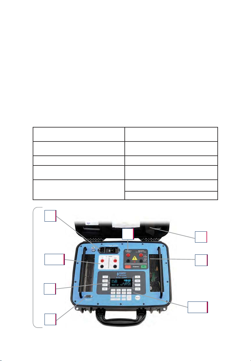
1. PRODUCT OVERVIEW
The MTS-2000 is a meter test system designed to test panel meters, transducers and
similar metering hardware.
All applicable quantities (voltage, current, power, frequency, phase, etc) are
displayed as required.
The MTS-2000 is designed to be easily operated from the controls on the front
panel. The system displays output values, operating modes, etc. The user interface
makes use of a “bank machine” type menu system that can be navigated with soft-
keys on the instrument. All current and voltage inputs and outputs use standard
banana jacks. The MTS-2000 can also be operated by remote control from an
external computer.
FEATURES:
1. 4x20 Character Display 6. Front Panel On/Off Switch and
120Vac Input
2. Front Panel Membrane with Bank
Machine Style Soft-key Interface 7. One RS-232 Port
3. Keypad for Data Entry 8. Cable Storage in Lid
4. 0-150V AC/DC Voltage
Output Channel 9. 0-20mA Analog Input
5. Convertible Voltage (0-150V AC or
DC) or Current (0-5Aac, 0-2.5Adc)
Output Channel
10. 0-20mA Analog Output
Boot Time < 5 Seconds
9/10
2/3
1
4
5
6
7
8

CU R001 01B MANTA TEST SYSTEMS 5
2. TECHNICALSUPPORT
Our technical support team is committed to working with you, our customers, to
ensure that you have the products which best serve your specic needs. The design
of this instrument reects decades of experience in the electric power industry.
Manta Test Systems recognizes, however, that there will be testing situations
encountered which were not considered during product design.
Manta Test Systems encourages any user questions, problems or suggestions to be
forwarded to us, via the representative through whom the product was purchased,
or directly to us via the fax numbers provided on the front cover or in the customer
support area of our website.
3. SAFETY CONSIDERATIONS
This instrument can generate high levels of current and voltage. Incorrect usage
may cause personal injury or damage to the instrument.
The user must be qualied to work safely in the intended application environment of
this instrument. Non-adherence to the following minimum requirements constitutes
misuse of the MTS-2000, and the manufacturer accepts no liability for damages
arising from such misuse:
1) The instrument case must always be effectively grounded. The integrity of
the power supply cord ground should always be veried before use.
2) All leads and connectors should be in good condition and rated for the
appropriate voltage and current carrying requirements.
3) The outputs must not be connected to live outputs or live equipment.
4) All outputs must be turned off before making changes in connections.
5) Note: the black (return) terminals of Channel 1 and 2 are internally connected.

6 MANTA TEST SYSTEMS CU R001 01B
4. LIMITED PRODUCT WARRANTIES
4.1 Hardware
Manta Test Systems warrants that its hardware products, and the hardware
components of its products, shall be free from defects in materials and workmanship
under normal use and service for a period of one year from the date such products
are shipped from Manta Test Systems.
Provided that Manta Test Systems receives notice of any defects in materials or
workmanship of its hardware products, or hardware components of its products,
within a one-year period, Manta shall, at its option, either repair or replace the
defective hardware product or hardware component, if proven to be defective.
4.2 Software & Firmware
Manta Test Systems warrants that its software products, and the software and
rmware components of its products, shall not fail to execute their programming
instructions under normal use and service, due to defects in materials and
workmanship, if properly installed on intended hardware, for a period of one year
from the date such products are shipped from Manta Test Systems.
Provided Manta Test Systems receives notice of such defects within the warranty
period, it shall, at its option, either repair or replace the software or rmware media,
if proven to be defective.
4.3 Separate Extended War ranty for Hardware Products
Aside from the standard warranty set forth above, Manta Test Systems offers a
separate extended warranty plan for all hardware products (excluding cables,
batteries and accessories) which may be purchased, and extends the standard
warranty by one additional year.
The extended warranty is issued under the same terms, conditions and exclusions
as the standard warranty set forth herein. Pricing is based upon the cost of the
product, and the average cost of servicing and calibration. Refer to the Manta Test
Systems price list available from your local representative, or Manta Test Systems,
for extended warranty pricing for specic products. The extended warranty must
be purchased and paid for within three months from the date the product is shipped
from Manta Test Systems.
4.4 Exclusi on of other Warranties
THE FOREGOING WARRANTIES ARE EXCLUSIVE, AND ARE IN LIEU
OF ANY AND ALL OTHER WARRANTIES (WHETHER WRITTEN, ORAL
OR IMPLIED) INCLUDING, BUT NOT LIMITED TO, WARRANTY OF
MERCHANTABILITY IN OTHER RESPECTS THAN AS SET FORTH ABOVE,
AND WARRANTY OF FITNESS FOR A PARTICULAR PURPOSE.

CU R001 01B MANTA TEST SYSTEMS 7
4.5 Limitati on of Liabili ty and Remedies
IT IS UNDERSTOOD AND AGREED THAT MANTA TEST SYSTEMS’
LIABILITY AND PURCHASER’S SOLE REMEDY, WHETHER IN CONTRACT,
UNDER ANY WARRANTY, IN TORT (INCLUDING NEGLIGENCE), STRICT
LIABILITY OR OTHERWISE, SHALL NOT EXCEED THE COST OF
REPAIR OR REPLACEMENT OF MANTA TEST SYSTEMS’ PRODUCTS,
AS SET FORTH ABOVE, AND, UNDER NO CIRCUMSTANCES, SHALL
MANTA TEST SYSTEMS BE LIABLE FOR ANY SPECIAL, INCIDENTAL,
OR CONSEQUENTIAL DAMAGES, INCLUDING, BUT NOT LIMITED
TO, PERSONAL INJURY, PROPERTY DAMAGE, DAMAGE TO OR LOSS
OF EQUIPMENT, LOST PROFITS OR REVENUE, COSTS OF RENTING
REPLACEMENTS, AND OTHER ADDITIONAL EXPENSES.
FURTHERMORE, IT IS UNDERSTOOD AND AGREED THAT MANTA TEST
SYSTEMS SHALL NOT BE LIABLE FOR ANY DAMAGES, LOSSES OR
EXPENSES AS A RESULT OF THE PURCHASER’S OR ANYONE ELSE’S:
I. NEGLIGENCE (WHETHER DEEMED ACTIVE OR PASSIVE),
II. MISUSE, ABUSE, OR MODIFICATION OF MANTA TEST SYSTEMS
PRODUCTS,
III. USE OR OPERATION OF PRODUCTS NOT IN CONFORMITY WITH
THE SPECIFICATIONS AND INSTRUCTIONS FURNISHED BY
MANTA TEST SYSTEMS FOR ITS PRODUCTS,
IV. REPAIR OR MAINTENANCE OF MANTA TEST SYSTEMS’
PRODUCTS BY PERSONS OR ENTITIES NOT AUTHORIZED BY
MANTA TEST SYSTEMS, OR
V. DAMAGE TO, OR DESTRUCTION OF, PRODUCTS, DURING
DELIVERY TO MANTA TEST SYSTEMS FOR ANY REASON.
4.6 Limitati on of Warrant y Regar di ng Software
Manta Test Systems does not warrant that the operation of the software, rmware or
hardware shall be uninterrupted or error free.
4.7 Extensi on of Warr anty
At the discretion of Manta Test Systems, the warranty may be extended for a product
which has been returned for service shortly after its warranty period has expired.

8 MANTA TEST SYSTEMS CU R001 01B
5. PRIMARYMODULES
5.1 Front Panel
The “bank machine” style user interface makes use of soft-keys that are selected by
pressing the button adjacent to the description. A keypad is used for direct entry of
numeric values.
5.2 Di splay
The system uses a 4x20 character vacuum orescent display device to display output
values, operating modes, etc.
5.3 RS-232 Communi cations
An RS-232 port is provided to allow control of the instrument using a PC and to
facilitate software upgrades.
5.4 DC Cur rent Loop Output
A 0mA to 20mA output is provided for testing current loops normally driven by a transducer.
5.5 DC Cur rent Loop Input
A –20mA to +20mA input is provided to measure a transducer’s output.
5.6 Channel s
The system houses two independent power output channels. One channel operates in
voltage mode only, and can generate up to 150V (AC or DC). The other channel can
generate voltage or current. In voltage mode it generates up to 150V (AC or DC).
In current mode it generates up to 5Aac or up to ±2.5Adc.
5.7 Power supply
The mains input is auto-ranging, power factor corrected and can operate from either
105-130 or 208-250Vac (50-60Hz).

CU R001 01B MANTA TEST SYSTEMS 9
6. SPECIFICATIONS
NOTE: Due to techinical progress, specications are subject to change without
notice. All AC quantities are RMS values, except as otherwise noted. Power
outputs are specied for nominal 120VAC/60Hz or 240VAC/50Hz power input,
and 25°C ambient operating temperature. Derating applies for lower input power
voltages and higher ambient temperatures.
For all current outputs, maximum obtainable current will vary inversely with load
impedance. For extended operation at high power output levels, ensure adequate
cooling (i.e. verify air intakes and exhaust ports are unrestricted).
6.1 Inputs
Mains Supply
Single phase 105-130VAC (or 208-250VAC) @400VA max, 47-63 Hz, auto-ranging
Transducer Input
Measures low level output from AC transducers
Maximum input level: ±20mA DC
Measurement accuracy: 0.04% reading + 0.01% range (25±5°C) after 10min warmup
(for waveforms under 2% THD )
Connector: 4mm Banana
6.2 Outputs
Transducer Output
Generates low level output for AC transducer inputs
Maximum output level: 0 - 20mA DC
Setting accuracy: 0.04% setting + 0.01% range (25±5°C) after 10min warmup
Compliance: >=10Vdc, ( >=11Vdc typical )
Max Load: 10kΩ (to 1mA), 2kΩ (to 4mA), 1kΩ (to 10mA), 500Ω (to 20mA
Connector: 4mm Banana
Voltage
2 AC or DC voltage channels
0-150V (AC or DC) per channel in independent mode
0-300V (AC or DC) when channels are connected in series
Setting resolution: 0.01Vrms, 0.1Vdc
Accuracy greater of: 0.25% of setting or 0.03 Vrms (10Hz-400Hz, DC)
1.0% of setting (400Hz-800Hz), greater than 1% of range
Power AC: 30VA max per channel, 60VA min with 2 channels in series,60Hz.
Power DC: 15W dc max per channel, 30W dc with 2 channels in series
Noise & distortion at maximum power: <1%
Bandwidth: 3kHz (-3dB)
Protection: Overload, short circuit, over-temperature, transient overvoltage, clip indication
Surge Current (DC mode): 1A maximum (limited)
Connector: 4mm Banana
Table des matières
Autres manuels Manta Équipement de test
Manuels Équipement de test populaires d'autres marques

SMART
SMART KANAAD SBT XTREME 3G Series Manuel utilisateur

Agilent Technologies
Agilent Technologies BERT Serial Manuel utilisateur

Agilent Technologies
Agilent Technologies N3280A Manuel utilisateur

Vernier
Vernier Go Direct Voltage Manuel utilisateur

Lifeloc
Lifeloc R.A.D.A.R. Manuel utilisateur

Fluke
Fluke T5-600 Instructions d'utilisation et d'installation