LSIS Ethernet option board Manuel utilisateur

Before using the product
Thank you for purchasing the Ethernet option board.

ii
Safety Information
Safety Information
•Carefully read and follow the safety guidelines below. They are provided to prevent
potential accidents and hazardous situations and ensure that you can operate this
product safely and correctly.
•Safety information is classified in two categories: ‘WARNING’ and ‘CAUTION.’
Refer to the following for the meaning of the safety information.
Indicates a potentially hazardous situation which, if not avoided, may cause death or
serious injury.
Indicates a potentially hazardous situation which, if not avoided, may cause minor
injury or damage to the product.
•Symbols used in this document and on the product indicate the following.
Read and follow instructions carefully to avoid dangerous situations.
Presence of "dangerous voltage"inside the product that may cause harm or electric
shock.
•After reading this user manual, keep it in an easily accessible place for future
reference whenever operators need it.
•Carefully ready this use manual to safely operate the LSLV- G100 series inverter
products. Ensure that this user manual is handed over to the next person who
operates and maintains the product.
•Be careful not to damage the CMOS elements on the PCB.
Static charge may damage the electronic components.
•Turn off the inverter before connecting or disconnecting network cables.
Communication errors or device failure may otherwise result.
•Install the network board correctly and ensure that it is firmly connected to the
inverter.
Communication errors or device failure may otherwise result.
•Check the parameter units when configuring the parameter values.
Communication errors may result if incorrect units are used.

iii
Table of Contents
Table of Contents
1Overview............................................................................................................... 1
2Technical Ethernet specifications ...................................................................... 2
3Package components .......................................................................................... 3
4External appearance and installation................................................................. 4
4.1 External appearance..................................................................................................4
4.2 Indication LEDs..........................................................................................................4
4.3 Installing the communication option board ................................................................5
5Network connection............................................................................................. 6
6Network cable specifications.............................................................................. 7
6.1 Frequency band.........................................................................................................7
6.2 Twisted pair cable types ............................................................................................7
7Keypad parameters related to Ethernet communication................................... 8
7.1 Communication option board version (Option version information, CM-06) ...........10
7.2 Communication option board LED status (FBus Led, CM-09) ................................10
7.3 Configuring the IP, subnet mask, and gateway addresses for the communication
option board (CM-10 to CM-21)...............................................................................11
7.4 Ethernet Speed (CM-22)..........................................................................................11
7.5 CIP input instance (CM-23) .....................................................................................11
7.6 CIP output instance (CM-24)...................................................................................12
7.7 Para status (CM-30 to CM-38).................................................................................12
7.8 Para control (CM-50 to CM-58) ...............................................................................13
7.9 Comm update (CM-94)............................................................................................13
8Inverter communication address...................................................................... 14
9Modbus/TCP Frame ........................................................................................... 15
9.1 Modbus/TCP frame structure...................................................................................15
9.2 Function codes.........................................................................................................16
9.2.1 Read Holding registers ..............................................................................16
9.2.2 Read Input registers ..................................................................................17

iv
Table of Contents
9.2.3 Write Single register ..................................................................................17
9.2.4 Write Multiple register................................................................................18
9.3 Exception (Except) frame ........................................................................................18
10EtherNet/IP.......................................................................................................... 20
10.1 Basic protocol structure ...........................................................................................20
10.2 Implicit message......................................................................................................21
10.2.1 Scope of support........................................................................................21
10.2.2 Input instances...........................................................................................21
10.2.3 Output Instance..........................................................................................24
10.3 Explicit messages....................................................................................................27
10.4 Supported objects....................................................................................................28
10.4.1 Identity Object (Class 0x01, Instance 1)....................................................28
10.4.2 Motor Data Objects (Class 0x28, Instance 1)............................................29
10.4.3 Control Supervisor Objects (Class 0x29, Instance 1)................................30
10.4.4 Inverter Objects (Class 0x2A, Instance 1).................................................33
10.4.5 Class 0x64 (Inverter Object) –Manufacture Profile...................................34
11Lost Command................................................................................................... 36
11.1 Inverter Keypad Parameter......................................................................................36
11.2 Modbus TCP Lost Command conditions.................................................................36
11.3 EtherNet/IP Lost Command conditions ...................................................................37
12LED Indications and troubleshooting............................................................... 38

Overview
1
1 Overview
The Ethernet option board enables the LSLV-G100 inverter to connect to an Ethernet
network.
The Ethernet option boards supports two Ethernet network protocols: Modbus TCP
and EtherNet/IP.
Using the network features, controlling and monitoring of the inverter can be
performed via a PLC sequence program or a master module. Because the Ethernet
option board supports Ethernet connection and the IPV4 protocol, remote control and
monitoring of the device is available from any place where Internet access is available,
as long as the inverter is connected to a network that is connected to the Internet via a
gateway.
With simple network cable wiring, installation times can be reduced and maintenance
becomes easier.
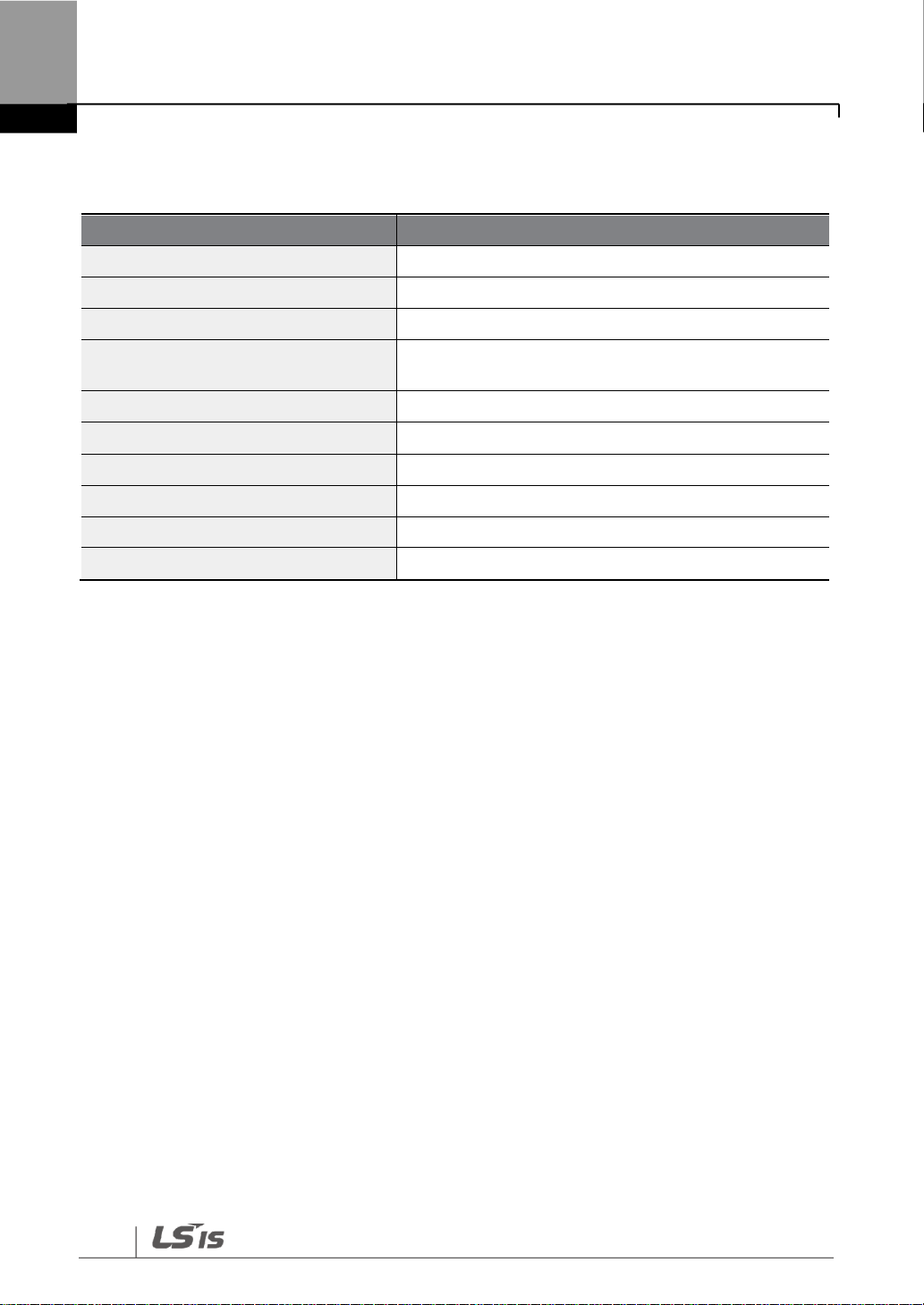
Technical Ethernet specifications
2
2 Technical Ethernet specifications
Items
Description
Network speed
100 Mbps
Transmission type
Baseband (half, full duplex)
Max. distance between nodes
100 m (between node and hub)
Max. number of nodes
Depends on the hub specification (Maximum
connected stations in a daisy chain: 64)
Auto negotiation
Supported
Max. frame size
1500 bytes
Communication zone access type
CSMA/CD
Frame error detection
CRC32
Recommended TCP socket
3 sockets
Recommended cable
UTP, FTP, STP (Refer to page 6)

Package components
3
3 Package components
Ethernet communication card (1 ea) / fixing bolt (1 ea) / user manual

External appearance and installation
4
4 External appearance and installation
4.1 External appearance
4.2 Indication LEDs
Green
LED0
Red
LED1
2Color
LED2
2Color
LED3

External appearance and installation
5
4.3 Installing the communication option board
1 Remove the front cover from the G100 inverter.
2 Connect the G100 inverter and the communication option board using an RJ-45 network
cable.
3 Hook up the communication option board to the installation slot.
4 Install the fixing bolt provided with the communication option board using an appropriate
tool.
5 The installation is complete.
•Ensure that the G100 inverter is turned off before installing or uninstalling the
Ethernet communication option board.
•Ensure that the electric charge in the capacitors inside the G100 inverter is
completely discharged before installing or uninstalling the Ethernet communication
option board.
•Ensure that the RJ-45 cable is firmly fixed to the inverter and the option board.
•Frame ground (FG) should not be used on the Ethernet communication option boards.

Network connection
6
5 Network connection
Communication network terminals
Pin no.
Signal
Description
Cable color
1
TX+
Data transmission (+)
White/Yellow
2
TX-
Data transmission (-)
Yellow
3
RX+
Data reception (+)
White/Green
4
NONE
Not used
Blue
5
NONE
Not used
White/Blue
6
RX-
Data reception (-)
Green
7
NONE
Not used
White/Brown
8
NONE
Not used
Brown
※The cables connected to pin 1 and pin 2 must be twisted in a pair.
※The cables connected to pin 3 and pin 6 must be twisted in a pair.
Table des matières
Manuels Carte réseau populaires d'autres marques


3Com
3Com EtherLink 3C509B Manuel utilisateur

TRENDnet
TRENDnet TEG-PCITX Manuel utilisateur

Cisco
Cisco MC16E Manuel utilisateur

Delta Electronics
Delta Electronics Braking Modules VFDB Series Manuel utilisateur

TwinMOS
TwinMOS Booming Manuel utilisateur

Dialogic
Dialogic Media Board DM/V1200BTEPEQ Manuel utilisateur

Buffalo
Buffalo AirStation WLI-PCM-L11GP Manuel utilisateur

National Instruments
National Instruments NI 9234 Manuel utilisateur

Hama
Hama 49276 Manuel utilisateur

Linksys
Linksys WCF54G - Wireless-G Compact Flash Card Manuel d'utilisation

Compaq
Compaq Wireless LAN 100 Manuel utilisateur

Bose
Bose PowerMatch Dante Manuel utilisateur