Logic PNM-220 Manuel utilisateur

Technical Manual 1.00, PNM-220
Technical Manual for the
PNM-220
Version 1.00
Logic IO ApS. Ph: (+45) 7625 0210
Ho mboes A é 14 Fax: (+45) 7625 0211
8700 Horsens Emai : info@ ogicio.com
Denmark www. ogicio.com / www.rtcu.dk
Page 1 of 16

Technical Manual 1.00, PNM-220
Introduction
The Logic IO PNM-220 is a comp ete so ution using the Navigation and Messaging
P atform designed for the most demanding and professiona f eet management
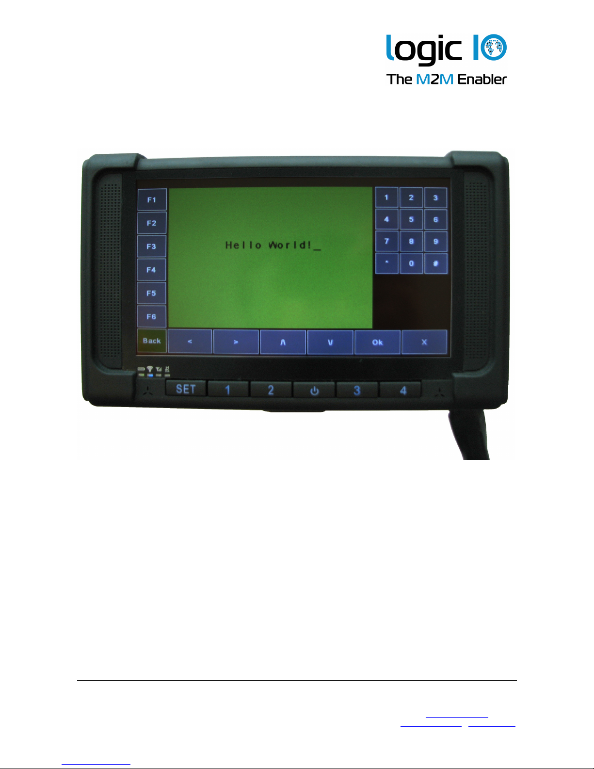
app ications. The PNM-220 device is a ruggedized 7-inch, easy to read, screen optimized
for finger touch usage. A powerfu processor and generous RAM and f ash ensure a
de ightfu experience. The PNM-220 a so offers support for connecting up to two cameras
used for rear-view or cabin view etc.
The PNM-220 comes with the PNM software/maps pre-insta ed and interface cab es for
the RTCU MX2i pro/pro+. Ready to go!
This technica manua describes the insta ation of the PNM-220, and the technica detai s
of the system. For contro ing the PNM device from the VPL user app ication, p ease refer
to the RTCU on ine he p, and for detai ed information on the NMP software interface,
p ease refer to the documentation of the Navigation and Messaging P atform.
The NMP software and the Sygic maps are pre-insta ed on the PNM device and activated
according to the user agreement. P ease refer to the NMP software documentation for
detai ed information.
Logic IO ApS. Ph: (+45) 7625 0210
Ho mboes A é 14 Fax: (+45) 7625 0211
8700 Horsens Emai : info@ ogicio.com
Denmark www. ogicio.com / www.rtcu.dk
Page 2 of 16

Technical Manual 1.00, PNM-220
Table of Contents
Introduction.............................................................................................................................2
Tab e of Contents...................................................................................................................3
Graphica view........................................................................................................................4
Package overview..................................................................................................................5
PNM-220 Overview............................................................................................................6
Typica System Connection................................................................................................8
Typica App ication.................................................................................................................9
Interfacing to the RTCU MX2i Pro/Pro+.............................................................................9
Ana og camera interface..................................................................................................10
Interfacing to the RTCU IDE Simu ator................................................................................11
Technica Specifications......................................................................................................12
Appendix A – Mounting the dashboard bracket...................................................................13
Appendix B – Insta ation and remova of the SD card........................................................15
Logic IO ApS. Ph: (+45) 7625 0210
Ho mboes A é 14 Fax: (+45) 7625 0211
8700 Horsens Emai : info@ ogicio.com
Denmark www. ogicio.com / www.rtcu.dk
Page 3 of 16
Technical Manual 1.00, PNM-220
Graphical vie
Logic IO ApS. Ph: (+45) 7625 0210
Ho mboes A é 14 Fax: (+45) 7625 0211
8700 Horsens Emai : info@ ogicio.com
Denmark www. ogicio.com / www.rtcu.dk
Page 4 of 16
Technical Manual 1.00, PNM-220
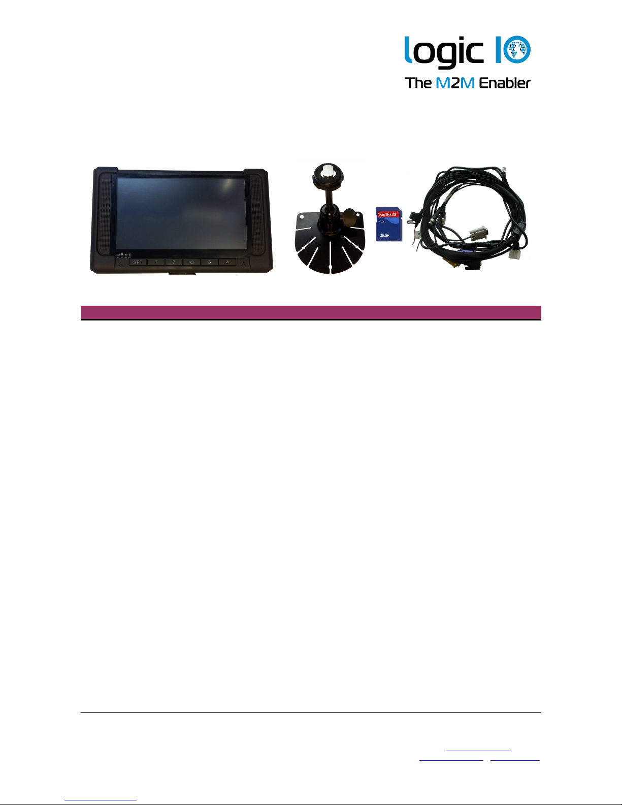
Package overvie
The PNM-220 package inc udes the fo owing items:
Quantity Item Description
1 PNM-220 device Windows CE6.0 device.
1 Mounting Bracket PNM-220 device mounting bracket
1 8 GB SD-CARD With pre-insta ed software.
Typica y a ready insta ed in the PNM-220
device.
1 PNM-220 series device cab e Connection cab e between PNM device and
the PNM interface box
Logic IO ApS. Ph: (+45) 7625 0210
Ho mboes A é 14 Fax: (+45) 7625 0211
8700 Horsens Emai : info@ ogicio.com
Denmark www. ogicio.com / www.rtcu.dk
Page 5 of 16

Technical Manual 1.00, PNM-220
PNM-220 Overvie
Interface Description
Power No bui t-in functiona ity. May be used for power by the app ication.
SET User-defined key.
Key 1 User-defined key.
Key 2 User-defined key.
Key 3 User-defined key.
Key 4 User-defined key.
LEDs 1 power LED and 3 status LEDs
Touch Screen To interact with the app ication using finger touch or attached sty us
P ease note that a the keys and the status LEDs on the PNM-220 device can be
configured by the VPL app ication. P ease refer to the RTCU IDE on ine-he p for further
information.
Logic IO ApS. Ph: (+45) 7625 0210
Ho mboes A é 14 Fax: (+45) 7625 0211
8700 Horsens Emai : info@ ogicio.com
Denmark www. ogicio.com / www.rtcu.dk
Touch
Screen
Power
Set Key2Key1 Key3 Key4
Speaker Speaker
LEDs
Page 6 of 16
Technical Manual 1.00, PNM-220
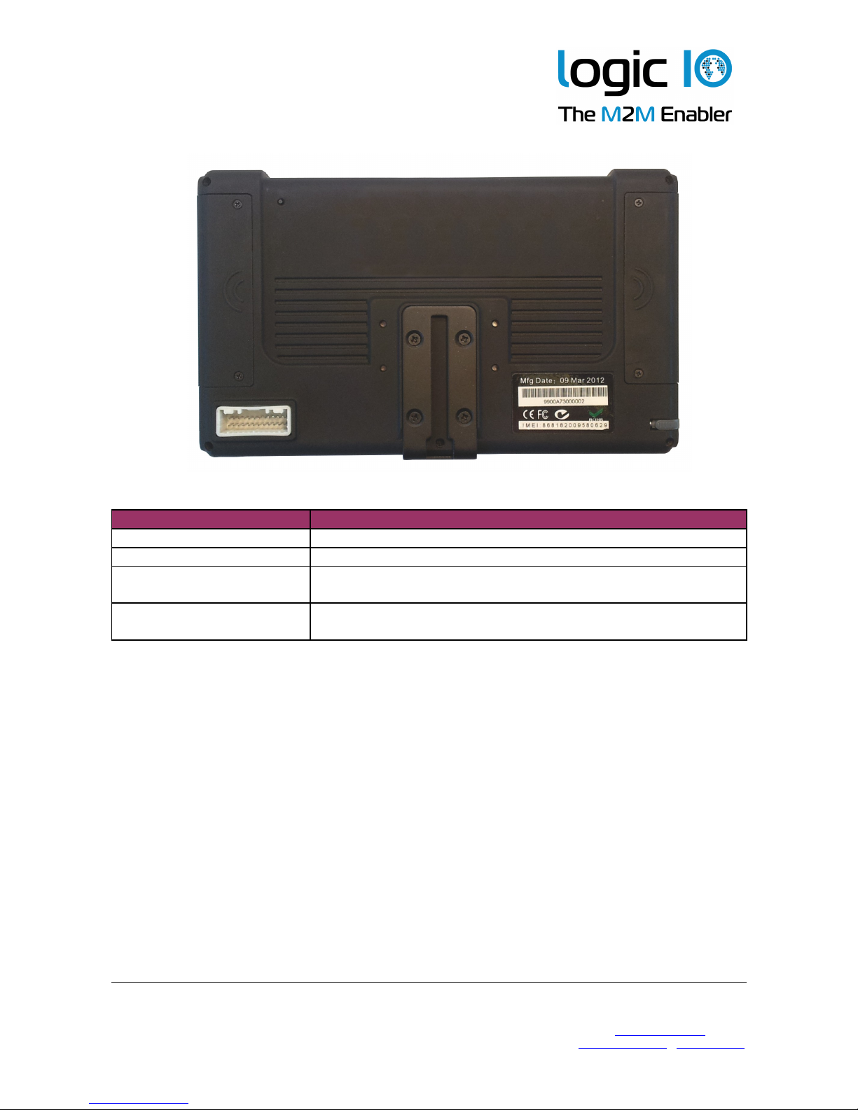
Interface Description
Reset Button Reset button of the PNM-220 device
Sty us Sty us for the touch screen
Interface Cab e
Connector
The connector for the PNM-220 device interface cab e
SD card compartment
Cover
The cover for the compartment where the SD card reader is
ocated.
The PNM-220 device can be reset asynchronous y using the reset button, ocated at the
backside of the device. P ease do not use the button un ess it is abso ute y needed.
The sty us can be used for more accurate hand ing of the touch screen. As the touch
screen is resistive, a finger can be used as we . The sty us is mounted tight y at the
backside of the device. It can be removed by s iding it out sideways.
Logic IO ApS. Ph: (+45) 7625 0210
Ho mboes A é 14 Fax: (+45) 7625 0211
8700 Horsens Emai : info@ ogicio.com
Denmark www. ogicio.com / www.rtcu.dk
Mounting
Jack
Sty us
Interface
Cab e
Connector
USB and
SD Card
Cover
Reset
Button
Page 7 of 16

Technical Manual 1.00, PNM-220
Typical System Connection
A typica system insta ation is i ustrated be ow:
The app ication in the RTCU unit contro s the power to the PNM device.
Un ike the other PNM devices with externa interface box, this device wi on y shut down
direct y whi e it is communicating with the RTCU. If asked to shut down whi e the
connection is ost, it wi either wait for a timeout1 before shutting down, or it can be
manua y shut down by pressing the reset button on the back. Note that the reset button
shou d not be used un ess abso ute y necessary, as it cuts the power immediate y, whi e
the two other ways a ows the device to perform a contro ed shut down.
1 See the setting DisconnectTimeout in the Navigation and Messaging P atform User Guide.
Logic IO ApS. Ph: (+45) 7625 0210
Ho mboes A é 14 Fax: (+45) 7625 0211
8700 Horsens Emai : info@ ogicio.com
Denmark www. ogicio.com / www.rtcu.dk
Page 8 of 16
RTCU Unit
Externa
Power Supp y

Technical Manual 1.00, PNM-220
Typical Application
This is a quick start guide to connect the PNM device to the supported RTCU units. It is
easy to insta the PNM system on ocation with the supp ied cab e for the RTCU MX2i
pro/pro+. The fo owing section wi describe the system connection to the supported
RTCU units.
Interfacing to the RTCU MX2i Pro/Pro+
The data cab e with the RJ-45 connector needs to be connected to the 8-po e seria port 2
connector on the RTCU unit. The power cab e, with the read and b ack wires at the end,
must be supp ied from an externa DC supp y.
An examp e of the connection to RTCU MX2i pro is shown in the drawing be ow.
1. Connect the PNM device interface cab e to the PNM device.
2. Connect the RJ-45 data cab e of the PNM device interface cab e to the seria Port 2
of the RTCU MX2i pro.
3. Connect the power supp y to the power connector cab e. The power requirement is
9..32VDC. The b ack wire is (-) and the red wire is (+).
Note that the power to the PNM device is contro ed by the RTCU MX2i pro
app ication. The modu e wi not power on un ess the RTCU MX2i pro is powered on
and the app ication enab es the modu e. P ease refer to the RTCU IDE on ine he p
for enab ing and using the NMP interface.
Logic IO ApS. Ph: (+45) 7625 0210
Ho mboes A é 14 Fax: (+45) 7625 0211
8700 Horsens Emai : info@ ogicio.com
Denmark www. ogicio.com / www.rtcu.dk
Page 9 of 16
9..32VDC
Data cab e
Power cab e

Technical Manual 1.00, PNM-220
Analog camera interface
PNM-220 offers connection for up to two ana og cameras using the BNC connectors
avai ab e at the PNM device interface cab e. Ana og camera #1 must be connected to the
cab e abe ed with BNC-1 and ana og camera #2 must be connected to BNC-2.
The use of the cameras is under fu contro of the VPL app ication. P ease consu t the
RTCU IDE on- ine he p for additiona information.
Logic IO ApS. Ph: (+45) 7625 0210
Ho mboes A é 14 Fax: (+45) 7625 0211
8700 Horsens Emai : info@ ogicio.com
Denmark www. ogicio.com / www.rtcu.dk
Page 10 of 16
Table des matières


