
Lofa CANplus 640c Manuel utilisateur

CANplus®640c Control Panel Operation Manual
October 2018
LOFA Document No. 463-3002-22

Disclaimer: The contents of this document are not to be used for advertising, publication, or promotional purposes. Citation
of trade names does not constitute an official endorsement or approval of the use of such commercial products. All product
names and trademarks cited are the property of their respective owners.
DESTROY THIS DOCUMENT WHEN NO LONGER NEEDED. DO NOT RETURN IT TO THE ORIGINATOR.

Table of Contents
1 Important Safety and Emissions Information .......................................................... 1
1.1 Safety Symbols ............................................................................................ 1
1.2 Safety Instructions ........................................................................................ 1
1.3 Auxiliary Engine Stop Disclaimer...................................................................... 2
1.4 General Emissions Disclaimer ......................................................................... 3
1.5 Exhaust Emissions Compliance Disclaimer ........................................................ 3
2 Overview ........................................................................................................... 4
3 Display .............................................................................................................. 6
3.1 Adjusting Lighting and Contrast ....................................................................... 6
3.2 Button Bar ................................................................................................... 7
3.3 Analog Gauge Pages..................................................................................... 7
3.4 Digital Gauge Pages...................................................................................... 8
3.5 Single Analog Gauge..................................................................................... 9
3.6 Active Alarms............................................................................................... 9
3.7 Alarm List.................................................................................................... 9
3.8 Service Timers ............................................................................................ 10
3.9 Menus ....................................................................................................... 10
3.9.1 Menu Tree........................................................................................... 11
3.9.2 Access Levels ...................................................................................... 13
4 Manual Operation............................................................................................... 15
4.1 Throttle Control ........................................................................................... 15
4.2 Ramp Throttle ............................................................................................. 16
4.3 Rotary Throttle Control.................................................................................. 16
4.4 Stopping the Engine ..................................................................................... 16
4.5 Autoramp™ ................................................................................................ 17
5 Configuration .................................................................................................... 19
5.1 Display Menu .............................................................................................. 19
5.2 LOFA CANplus®Software Suite and LOFA CANplus®Config kit ............................ 19
5.3 LOFA CANplus®Software Suite and a USB drive ............................................... 20
6 Miscellaneous ................................................................................................... 21
6.1 Emissions System Functionality ...................................................................... 21
6.2 CP640c Panel Wiring.................................................................................... 21
6.2.1 Typical J1939 Wiring Topology ................................................................... 21
6.2.2 Engine Harness Connector ....................................................................... 22
6.2.3 Sealed Connectors ................................................................................ 22
6.2.4 Unsealed Connectors ............................................................................. 22
Page ii LOFA document No. 463-3002-22 Page ii

6.2.5 Harness Routing ................................................................................... 24
6.3 Engine Starter Excitation Connection ............................................................... 24
6.3.1 Starter Relay........................................................................................ 24
6.3.2 Battery Circuit Requirements..................................................................... 24
6.3.3 Battery Positive Connection ...................................................................... 24
6.3.4 Voltage Drop ........................................................................................ 25
6.3.5 Suppression of Voltage Transients (Spikes) .................................................... 25
6.3.6 Welding on Equipment with Electronic Controls ............................................... 25
6.4 Control System Troubleshooting...................................................................... 26
6.4.1 Testing a Warning or Shutdown .................................................................. 27
6.4.2 Testing CAN ........................................................................................ 27
6.5 Diagnostic Trouble Codes (DTC) ..................................................................... 27
6.5.1 Typical SPNs ....................................................................................... 27
6.5.2 FMI................................................................................................... 27
LOFA document No. 463-3002-22 Page iii

This page has been intentionally left blank.
1. Important Safety and Emissions Information
1 Important Safety and Emissions
Information
1.1 Safety Symbols
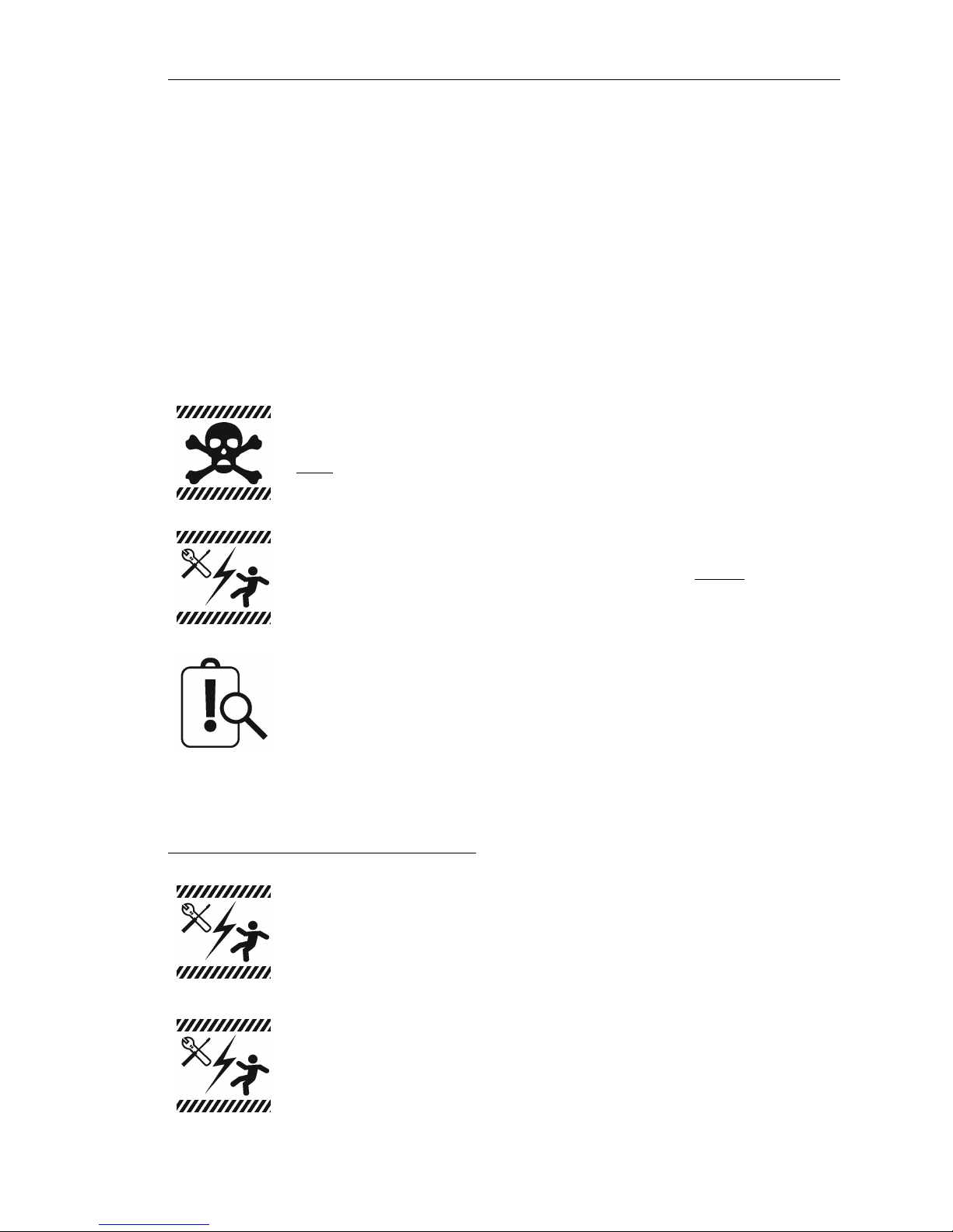
This manual uses the following conventions to present IMPORTANT SAFETY INFORMATION to you.
Please read and follow ALL SAFETY INSTRUCTIONS.
IMPORTANT AND URGENT SAFETY INFORMATION - A HAZARD THAT
WILL, IF NOT AVOIDED, CAUSE SERIOUS INJURY OR LOSS OF LIFE.
IMPORTANT SAFETY INFORMATION - A HAZARD THAT
MIGHT
CAUSE
SERIOUS INJURY OR LOSS OF LIFE.
ADDITIONAL IMPORTANT INFORMATION
1.2 Safety Instructions
Please read and follow all safety instructions.
This document must be completely read and understood prior to installing,
testing, or operating the equipment described within. Further, this document
must be retained for current and future users of this equipment. Failure to
strictly follow the warnings and dangers presented within this document
could result in damage to equipment, damage to property, bodily injury or
death.
LOFA products are not designed or approved for use as critical components
of any safety device or system that is intended to prevent bodily injury,
protect life, or prevent property damage.
LOFA document No. 463-3002-22 Page 1

1. Important Safety and Emissions Information
The specifying Original Equipment Manufacturer (OEM) and/or installer of
any LOFA panel is responsible for all safety labeling and operator education
regarding the safe operation of this panel and the operation of the specific
machine that this panel is installed upon including conformance to exhaust
emissions regulations.
LOFA products are not designed for, or intended for use on, applications
requiring explosive proof components. Further, LOFA products are not
designed for, or intended for application within, hazardous or explosive
environments.
The installer of this LOFA product is solely responsible for ensuring that
all OSHA, ANSI, CE, or other applicable standards are met with respect
to LOFA panel applicability, machine guarding, general safety guidelines,
labeling, and warnings.
The installer of this LOFA panel and/or LOFA harness is responsible for the
correct sizing and integration of a suitable fuse/breaker on the un-switched
DC circuit supplying power to the LOFA panel.
Only trained and qualified persons may perform installation, testing, service,
or repair work on the LOFA product.
The seller hereby expressly disclaims all warranties, either expressed or
implied, including any implied warranty of merchantability or fitness for a
particular purpose, and neither assumes nor authorizes any other person
to assume for it any liability in connection with the sale of such products.
Please refer to www.LOFA.net for details on LOFA Industries, LLC warranty
policies.
LOFA Industries, LLC has provided this document as a reference. We
try to keep this document updated with the latest information regarding
your LOFA product. However, changes do occur and LOFA reserves the
right to make changes to the design of the LOFA products and supporting
documentation without notice.
Page 2 LOFA document No. 463-3002-22 Page 2
1. Important Safety and Emissions Information
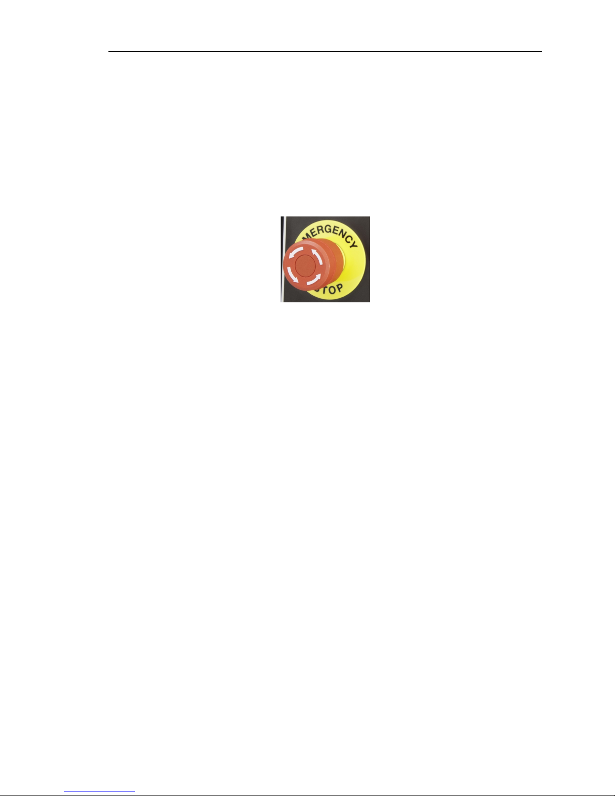
1.3 Auxiliary Engine Stop Disclaimer
This panel or harness may include an optional Auxiliary Engine Stop feature.
Please note that
the Auxiliary Engine Stop feature is NOT intended to function as the machine/equipment
Emergency Stop or be purposed as an Emergency Stop for safety purposes.
The machine
manufacturer must provide a separate Emergency Stop switch to meet safety mandates or emer-
gency machine shutdown functionality. The sole design intent of the Auxiliary Engine Stop Feature
is to provide for engine shutdown in the event of a keyswitch malfunction. The panel key/lever switch
should always be used as the primary engine shutdown method.
1.4 General Emissions Disclaimer
This panel may include provision(s) for operator input such as FORCE REGENERATION, INHIBIT
REGENERATION, INTERLOCK, and others specific to US and International emissions regulations.
Responsibility for emissions-related inputs and compliance with emissions regulations is solely that
of the owner and/or operator of the machine/engine on which this panel is connected.
1.5 Exhaust Emissions Compliance Disclaimer
This panel is equipped with operator-programmable parameters. The engine/machine as a function
of the emissions system can/could initiate, via the engine ECU (engine control unit), certain required
emissions operations such as regeneration of the DPF (diesel particulate filter), or other emissions
system maintenance, while the engine is running. The owner/operator of the engine/machine is
solely responsible for any adverse effects or damage to the engine, engine emissions system, or
other damage that could occur as a result of starting or stopping the engine/machine during any
ECU initiated emissions event.
LOFA document No. 463-3002-22 Page 3

2. Overview
2 Overview
The LOFA CP640c control panel is an economical platform for EPA Tier 3, EPA Tier 4 (interim), and
EPA Tier 4 electronically governed diesel engines. Graphical gauge pages or a single large analog
gauge are displayed on the 3.5-inch diagonal LCD. Virtually any SAE J1939 parameter reported
by the ECU (Engine Control Unit) can be displayed including, but not limited to: RPM, coolant
temperature, oil pressure, engine hours, voltage, exhaust emissions system state, and diagnostic
codes. The backlit display is clearly readable in both bright sunlight as well as total darkness and
housed in a rugged IP66 rated housing. The CP640c can optionally include three (3) bright LEDs to
indicate Faults, Warnings, and Emission-Related Alerts.
All components are installed in a heavy-duty, vibration isolated, metal enclosure designed to with-
stand the most extreme industrial applications. External weather resistant switches and controls
facilitate convenient operator inputs/controls. Active fault conditions are displayed in plain language
on popup messages and can be viewed in the fault list. Various diagnostic screens allow detailed
investigation of the CAN bus data stream.
All diagnostic and emissions related messages displayed on the CP640c
are generated by the engine ECU or other attached devices. The operator
must be familiar with the engine manufacturer ECU messages and icons in
order to react accordingly with respect to emissions compliance, service,
and diagnostic message response.
Page 4 LOFA document No. 463-3002-22 Page 4

2. Overview
LOFA document No. 463-3002-22 Page 5
Table des matières
Autres manuels Lofa Panneau de contrôle


