Lipper Flow Max Manuel utilisateur

Flow Max™ Faucets
OEM INSTALLATION MANUAL

Rev: 08.24.21 Page 2 CCD-0004349
TABLE OF CONTENTS
Introduction 2
Safety 2
Resources Required 3
Installation 3
With Metal Collar 3
With Plastic Collar 5
Operation 6
Fixed Faucet 6
Pull Down Faucet 7
Introduction
This manual outlines the installation and operation of the Flow Max Faucets.
Note: Images used in this document are for reference only when assembling, installing and/or operating
this product. Actual appearance of provided and/or purchased parts and assemblies may differ.
The "WARNING" symbol above is a sign that a procedure has a safety risk involved and may cause
death or serious personal injury if not performed safely and within the parameters set forth in this
manual.
Failure to follow instructions provided in this manual may result in death, serious personal injury
and/or severe product and property damage, including voiding of the component warranty.
Always wear eye protection when performing service, maintenance or installation procedures.
Other safety equipment to consider would be hearing protection, gloves and possibly a full face
shield, depending on the nature of the task.
The “CAUTION” symbol above is a sign that a safety risk is involved and may cause personal injury
and/or product or property damage if not safely adhered to and within the parameters set forth
in this manual.
Safety
Read and understand all instructions before installing or operating this product. Adhere to all safety labels.
This manual provides general instructions. Many variables can change the circumstances of the instructions,
i.e., the degree of difficulty, operation and ability of the individual performing the instructions. This
manual cannot begin to plot out instructions for every possibility, but provides the general instructions,
as necessary, for effectively interfacing with the device, product or system. Failure to correctly follow the
provided instructions may result in death, serious personal injury, severe product and/or property damage,
including voiding of the Lippert limited warranty.
Rev: 08.24.21 Page 3 CCD-0004349
Resources Required
• Phillips screwdriver
• Adjustable wrenches
• Flashlight
• Safety glasses
Installation
With Metal Collar
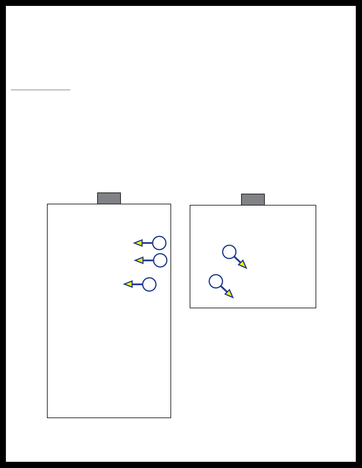
1. Unscrew the metal collar with the two screws from the faucet base and set aside (Fig. 1A).
2. Remove the metal washer (Fig. 1B) from the base and set aside.
Note: Leave black rubber washer (Fig. 1C) on faucet.
3. Place the faucet supply lines through the mounting hole on the deck, making sure the black rubber
washer and faucet base are seated firmly on the deck of the sink (Fig. 2A).
4. Position the faucet base so the handle is to the right side of the faucet base (Fig. 2B).
Fig. 1
A
B
C
Fig. 2
A
B
Placing the handle in the middle may cause severe burns depending on where the faucet neck is
positioned when turning on the water.
Rev: 08.24.21 Page 4 CCD-0004349
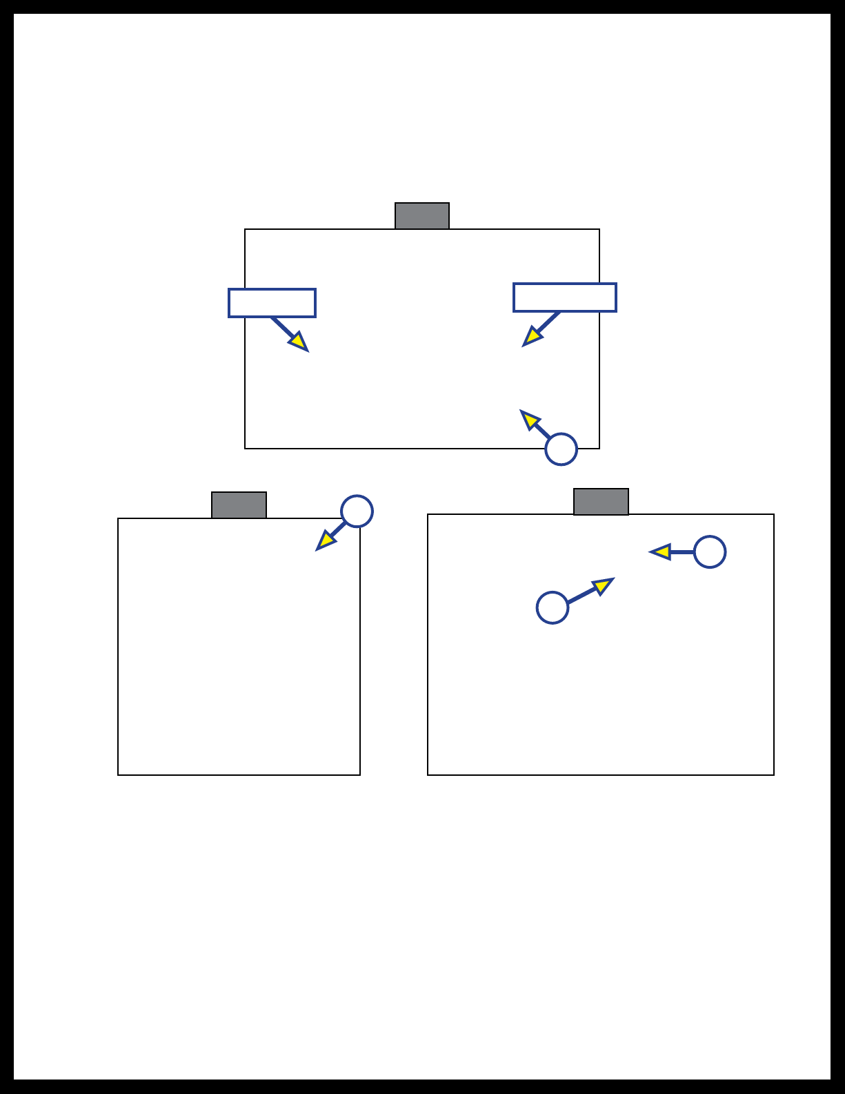
5. Under the sink, slide the metal washer (Fig. 1B) over the supply lines onto the base of the faucet. Make
sure the metal washer is flush against the underside of the sink deck and covering the mounting hole
(Fig. 3A).
6. Make sure the two screws on the collar are evenly inserted and are flush with the top of the
collar(Fig. 4A).
7. Screw the collar onto the faucet base all the way up to the metal washer (Fig. 5A).
Note: Make sure the handle of the faucet is placed in the desired position.
8. Using a Phillips screwdriver, tighten the two screws (Fig. 5B) on the collar to hold the collar into place.
Note: The red marked supply line is for hot water and the blue marked supply line is for the cold water.
9. Thread the nut on the hot water supply line onto the hot water outlet supply valve and tighten with an
adjustable wrench. Do not over tighten.
10. Thread the nut on the cold water supply line onto the cold water outlet supply valve and tighten with
an adjustable wrench. Do not over tighten.
11. Turn the hot and cold water outlet supply valves back on and check for any leaks.
Fig. 4 Fig. 5
A
A
B
Faucet base
A
Sink deck
Be sure to keep dirt and debris from entering the water supply lines as this could cause irregular
water ow.
Fig. 3
Rev: 08.24.21 Page 5 CCD-0004349
With Plastic Collar
1. Unscrew the black plastic collar from the faucet base and slide off from the faucet assembly.
Note: Wiggle the plastic collar off the supply lines one line at a time.
2. Slide the clear plastic washer off the faucet assembly.
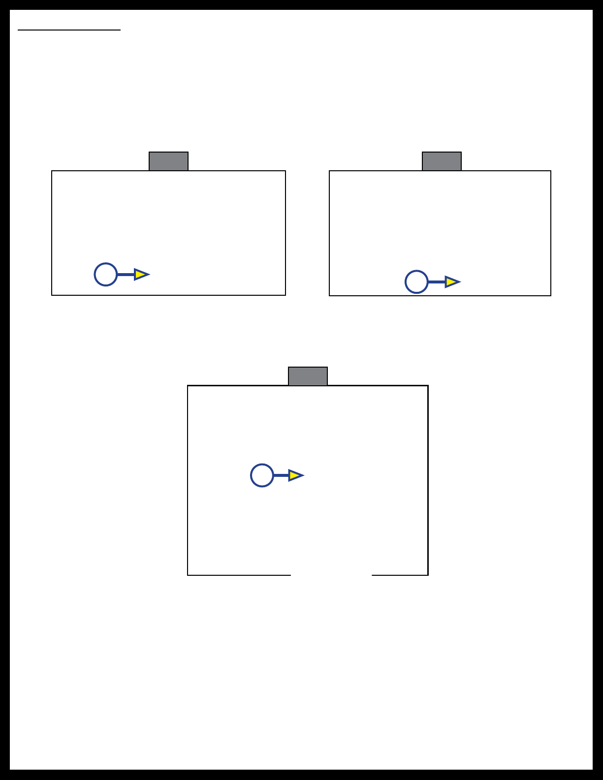
3. Place the faucet supply lines through the mounting hole on the deck, making sure the black rubber
washer and faucet base are seated firmly on the deck of the sink (Fig. 6A).
4. Under the sink, slide the clear plastic washer over the supply lines up to the underside of the sink deck
and covering the mounting hole (Fig. 7A).
Fig. 6 Fig. 7
A
5. Slide the black plastic collar back onto the supply lines, inserting one supply line at a time.
Note: Make sure the inside threads of the black plastic collar are at the top.
6. Screw the black plastic collar all the way up the faucet base until it will no longer turn (Fig.8A).
A
Note: The red marked supply line is for hot water and the blue marked supply line is for the cold water.
7. Thread the nut on the hot water supply line onto the hot water outlet supply valve and tighten with an
adjustable wrench. Do not over tighten.
8. Thread the nut on the cold water supply line onto the cold water outlet supply valve and tighten with
an adjustable wrench. Do not over tighten.
9. Turn the hot and cold water outlet supply valves back on and check for any leaks.
Be sure to keep dirt and debris from entering the water supply lines as this could cause irregular
water ow.
A
Fig. 8
Rev: 08.24.21 Page 6 CCD-0004349
Operation
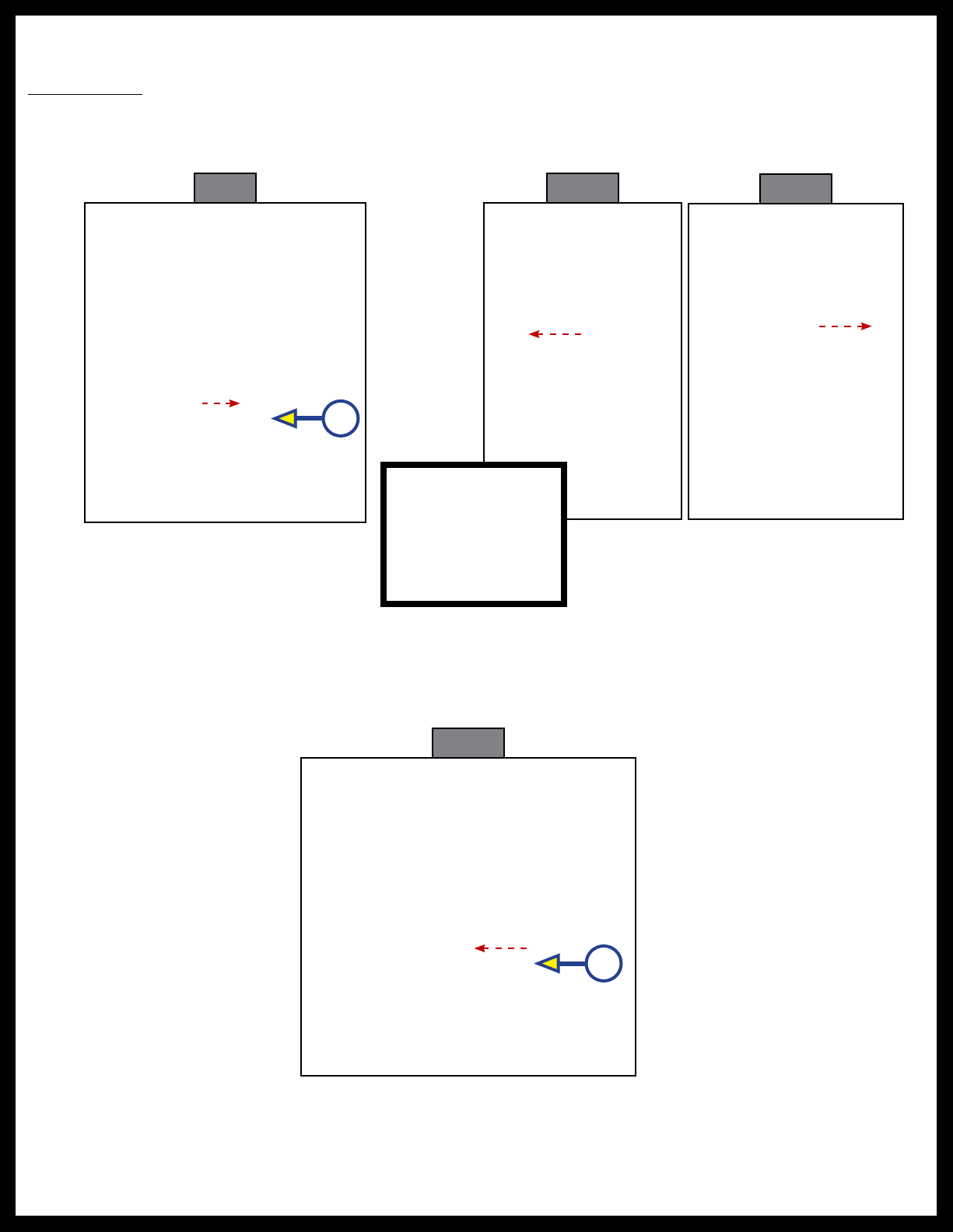
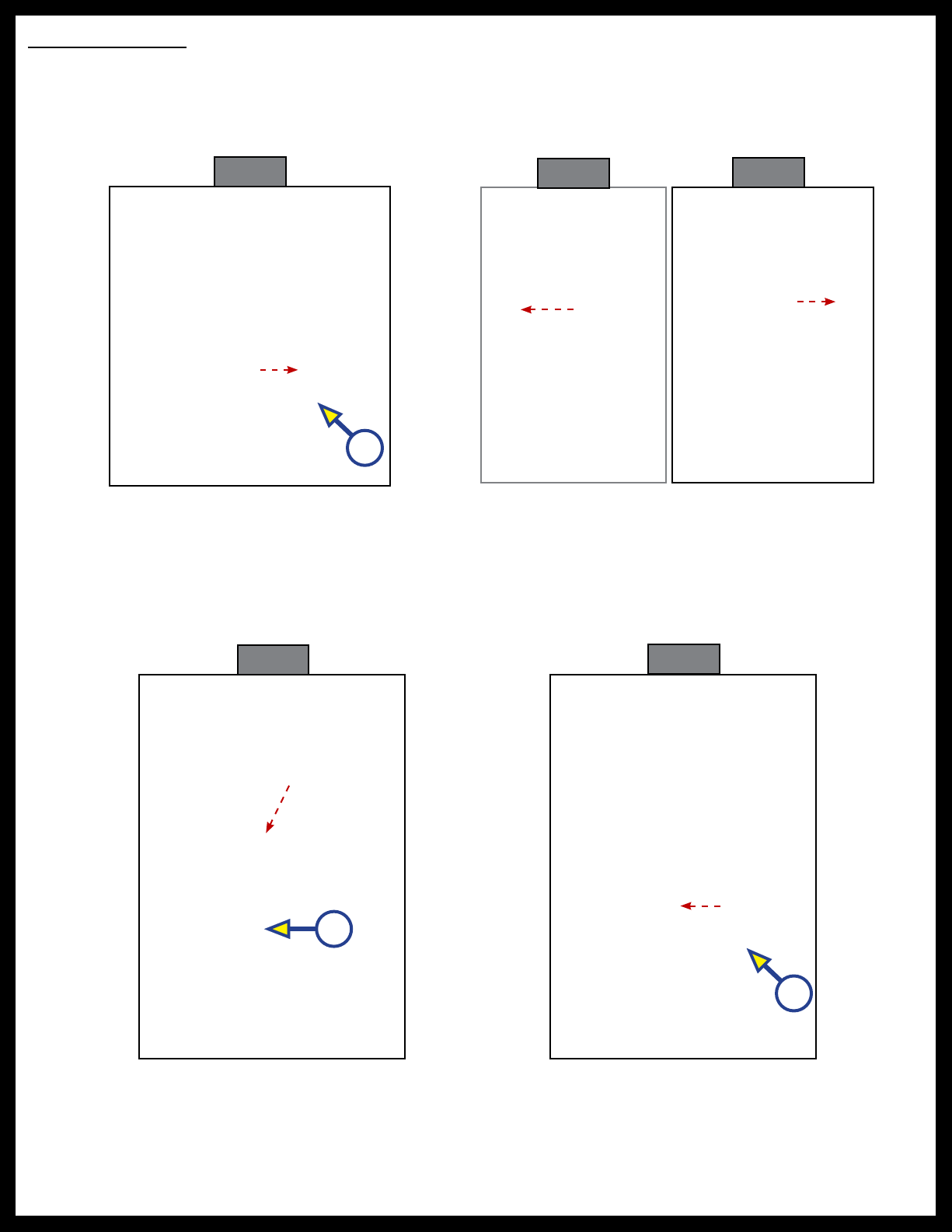
Fixed Faucet
1. Pull the lever away from the faucet to turn it on (Fig. 9A).
2. Move the lever towards you for hot water (Fig. 10) and away from you for cold water (Fig. 11).
Note: Located on the front of the lever is a “H” for hot water and a “C” for cold water. Move the lever in the
direction of the desired temperature.
3. Push the lever in towards the faucet to shut the water off (Fig. 12A).
Fig. 12
A
A
HC H C
Fig. 9 Fig. 10 Fig. 11
Rev: 08.24.21 Page 7 CCD-0004349
Pull Down Faucet
1. Pull the lever away from the faucet to turn it on (Fig. 13A).
2. Move the lever towards you for hot water (Fig. 14) and away from you for cold water (Fig. 15).
Note: Located on the front of the lever is a “H” for hot water and a “C” for cold water. Move the lever in the
direction of the desired temperature.
3. To use the spray wand pull down and out on the faucet head.
4. Press and release the button in on the lower portion of the faucet head (Fig. 16A) for spray mode. Press
and release the button again for stream mode.
5. Replace the faucet head by gently guiding the hose back into the faucet neck and insert into clip, if
applicable.
6. To shut the water off push the lever in towards the faucet (Fig. 17).
HC H C
Fig. 13 Fig. 14 Fig. 15
Fig. 16
A
A
A
Fig. 17

The contents of this manual are proprietary and copyright protected by Lippert Components, Inc. (LCI).
LCI prohibits the copying or dissemination of portions of this manual unless prior written consent from an
authorized LCI representative has been provided. Any unauthorized use shall void any applicable warranty.
The information contained in this manual is subject to change without notice and at the sole discretion of LCI.
Revised editions are available for free download from lippert.com.
Please recycle all obsolete materials.
For all concerns or questions, please contact
Lippert Components, Inc.
Table des matières


