Lionel 153IR Manuel utilisateur

71-4111-250
3/15
#153IR Controller
Owner’s Manual
#153IR Controller
Owner’s Manual

2
Table of contents
Installing and powering your 153IR Controller 3-7
Wiring accessories with your 153IR Controller 8-9
Choosing a location for your 153IR Controller 10
Adjusting your 153IR Controller 11-12
Accessory and signal wiring examples 13-18
Notes 19
Limited Warranty/Lionel Service 20
Congratulations on your purchase of the Lionel 153IR Controller. Place this device on any
Lionel O or O-27 gauge three-rail layout to activate any track side accessory. The 153IR
Controller uses an infrared beam to detect passing trains, cueing the device to activate your
signals and accessories. The 153IR Controller was built to provide years of reliable operation.
Congratulations!
The following Lionel marks are used throughout this Owner’s Manual and are protected under
law. All rights reserved.
Lionel®, LionChief™, LionChief Plus™,TMCC®, LEGACY®, FasTrack®,TrainMaster®, Odyssey®,
RailSounds®, CrewTalk™, TowerCom™, DynaChuff™, StationSounds™, Pullmor®, ElectroCoupler™,
Magne-Traction®, CAB-1®Remote Controller, American Flyer®, Lionel ZW®, ZW®, MagniVision®,
TMCC®, Lionelville®, Wireless Tether™, Powerhouse™, LionMaster®, Conventional Classics™, Postwar
Celebration Series™, TruRail™, PH-1 Powerhouse®, Powermaster®, Powerstation-Powerhouse®,
Accessory Motor Controller™, AMC™, Accessory Switch Controller™, ASC™, Action Recorder
Controller™, ARC™, Track Power Controller 300™, TPC 300™, Track Power Controller 400™, TPC
400™, Block Power Controller™, BPC™, Operating Track Controller™, OTC™, FatBoy™, Lionel
Lines®, Joshua Lionel Cowen Series™, Lockon®, TrainSounds™, MultiHorn™, MultiWhistle™,
Choo-Choo™, SensorTrack™, Plug-Expand-Play™, Imagineering™, SensorCar™, LionScale™

3
Installing and powering your 153IR Controller
Your 153IR Controller must be powered to control the infrared detection circuit and also to
provide power to the accessory it is controlling. There are two ways to accomplish this.
Powering the 153IR and the accessory from the track
You can power the 153IR and the accessory from the track. To accomplish this use the two
wires with Fastrack compatible terminals to connect the wires to the underside of any Fastrack
straight or full curve section. The red terminal connects to the center rail. The black terminal
connects to the outside rail. See figure 1 below.
BLACK WIRE
Connections are made under FasTrack
RED WIRE
Figure 1. Wire connections with FasTrack

4
Installing and powering your 153IR Controller continued
To make the proper connections to the auxilary power terminals, you need the ends of
the wires to be stripped back 1/4” to 3/8”. To strip the wires, use a pair of wire strippers
or a sharp knife. Only an adult should perform this task! Always use care when strip-
ping wires.
If you are using tubular track, simply cut off the slide on terminals and strip the wires back. Connect
the black wire with the white tracer to a Universal Lockon (6-24213) for the center rail. Connect the
solid black wire to the outside rail. See figure 2 below.
Caution
BLACK WIRE
BLACK WITH WHITE TRACER WIRE
Figure 2. Wire connections with Tubular track
5
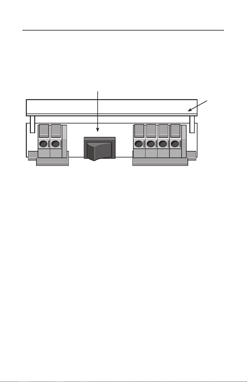
If you chose to power your 153IR using method 1 above, open the long hatch on the back side of the
153IR base and move the switch to the “Track Power” position. (If the switch is not in the track power
position the 153IR will not function, providing it is powered from the track). See figure 3 below.
Installing and powering your 153IR Controller continued
TRACK
POWER
AUX
POWER
ACC
PWR
ACC
GND
NO
NC
A
U
FLIP UP DOOR
POWER SELECTION
SWITCH
Figure 3. Back of the 153IR with the power selection switch in the TRACK POWER position

6
Installing and powering your 153IR Controller continued
Powering the 153IR and the accessory from an auxiliary AC power
transformer
You can power the 153IR and the accessory from an auxiliary AC power transformer. If you use
auxillary power, do not connect the track wires to the track. Refer to figure 4 below for proper-
ly wiring the 153IR to an accessory power transformer. It is very important you get the polarity
correct for your accessory to operate properly.
To make the proper connections to the auxilary power terminals, you need the ends of
the wires to be stripped back 1/4” to 3/8”. To strip the wires, use a pair of wire strippers
or a sharp knife. Only an adult should perform this task! Always use care when strip-
ping wires.
Caution
TRACK
POWER
AUX
POWER
ACC
PWR
ACC
GND
NO
NC
A
U
BLACK WIRE
RED WIRE
Figure 4. 153IR connected to a transformer
Set the input voltage to the 153IR Controller to 12-14 VAC (you can increase this input voltage if the
accessory you have it connected to requires more power than 12 to 14 Volts).

7
Installing and powering your 153IR Controller continued
If you chose to power your 153IR using an auxilary AC power transformer, open the long hatch on
the back side of the 153IR base and move the switch to the “Aux Power” position. (If the switch is
not in the aux power position the 153IR will not function, providing it is powered from an accessory
transformer). See figure 5 below.
TRACK
POWER
AUX
POWER
ACC
PWR
ACC
GND
NO
NC
A
U
POWER SELECTION
SWITCH
Figure 5. Back of the 153IR with the power selection switch in the AUX POWER position
FLIP UP DOOR

Wiring accessories with your 153IR controller
8
Accessories are only connected to the terminals labeled “ACC PWR”, “ACC GND”, “NO”
and “NC”. NO is “Normally Open” and is not powered until the 153IR detects a train. NC
is Normally Closed and is powered until the 153IR detects a train. When the 153IR detects a
train the NC output turns off and the NO output turns on. When the train passes and the
153IR deactivates the NO output turns off and the NC output turns on again. Figure 6 below
illustrates where these terminals are located. The ACC PWR terminal provides power to your
accessory (AC Hot or red). The ACC GND terminal provides AC Ground to your accessory (AC
Ground/U/black) at all times.
Do not use a wire larger than 24 gauge!
Note
TRACK
POWER
AUX
POWER
ACC
PWR
ACC
GND
NO
NC
A
U
AUXILARY POWER
SUPPLY
ACCESSORY TERMINALS
FLIP UP DOOR
POWER SELECTION
SWITCH
ACC PWR NO
ACC GND NC
Figure 6. 153IR wire terminals and connections

9
Wiring accessories with your 153IR controller continued
Table 1 provides the basic wiring for various accessories (lamps, sounds, animation, etc.). Some
accessories feature only one animation such as a light that turns on and off. Other accessories feature
two animations such as a light and some type of motion (a gateman figure for instance).
Refer to the specific wiring examples that appear on pages 12- 15 to help determine which
accessory terminals control the different accessory animations.
Power is constantly ON POWER terminal on the accessory connected
to the ACC PWR terminal
GROUND terminal on the accessory connected
to the ACC GND terminal
Power is ON until triggered by the train POWER terminal on the accessory connected
to the ACC PWR
GROUND terminal on the accessory connected
to the NC terminal
Power is OFF until triggered by the train POWER terminal on the accessory connected to
the ACC PWR
GROUND terminal on the accessory connected
to the NO terminal
Table 1. Accessory option and wiring configurations

10
Choosing a location for your 153IR controller
With the 153IR Controller you are able to activate signals and accessories for more proto-
typical operation of your layout. Position your 153IR Controller so that the train will
trigger the 153IR to activate the accessory before the train arrives. For example, if your train
is moving from left to right (in figure 7 below), position the 153IR to the left side of the
accessory so that the train triggers the activation before the train arrives where the accessory
is placed. (In this instance we use a grade crossing gate and signal).
DIRECTION OF TRAIN
DIRECTION OF TRAIN
GATE 2
BLACK WIRE
BLACK WIRE
GATE 1
153 IR CONTROLLER
153 IR CONTROLLER
SIGNAL
Figure 7. Single 153IR Controller location
Figure 8. Signal and 153IR Controller locations
If you are using a block signal you may want the signal to change from green to red once the train
passes the signal. In this instance you will want to place the 153IR after the signal itself. Refer to
figure 8 below.
BLACK WITH
WHITE TRACER
WIRE
BLACK WITH
WHITE
TRACER
WIRE
Autres manuels Lionel Contrôleurs

Lionel
Lionel LCS AMC2 Manuel utilisateur

Lionel
Lionel SC-2 Manuel utilisateur

Lionel
Lionel Legacy PowerMaster 360W Manuel utilisateur

Lionel
Lionel TMCC BPC Manuel utilisateur

Lionel
Lionel DZ-2500 Manuel utilisateur

Lionel
Lionel TMCC Manuel utilisateur

Lionel
Lionel CSM2 Manuel utilisateur

Lionel
Lionel LCS BPC2 Manuel utilisateur

Lionel
Lionel RAILROAD Manuel utilisateur


