
LinMot B1100-PP Manuel utilisateur


inMot Installation Guide
© 2012 NTI AG
This work is protected by copyright.
Under the copyright laws this publication may not be reproduced or transmitted in any form electronic or mechanical including
photocopying recording microfilm storing in an information retrieval system not even for didactical use or translating in whole or in
part without the prior written consent of NTI AG.
LinMot® is a registered trademark of NTI AG.
The information in this documentation reflects the stage of development at the time of press and is therefore without obligation.
NTI AG reserves itself the right to make changes at any time and without notice to reflect further technical advance or product
improvement.
Document version 3.16/ Ro February 2012
NTI AG / inMot®www. inMot.com Page 2/19
B1100 Installation Guide

inMot Installation Guide
Table of Content
1 Important safety notes for B1100 series controllers....................................................4
2 System Overvie .............................................................................................................5
3 B1100 Interfaces...............................................................................................................6
4 Functionality.....................................................................................................................7
5 Soft are............................................................................................................................7
6 Po er Supply and Grounding........................................................................................8
7 Description of the connectors / Interfaces....................................................................9
7.1 X1................................................................................................................................9
7.2 X2................................................................................................................................9
7.3 X3..............................................................................................................................10
7.4 X5..............................................................................................................................11
7.5 X7 - X8......................................................................................................................12
7.6 X13............................................................................................................................12
7.7 X14............................................................................................................................13
7.8 LEDs.........................................................................................................................14
7.9 S4..............................................................................................................................14
8 Physical Dimension.......................................................................................................15
9 Po er Supply Requirement..........................................................................................16
10 Ordering Information...................................................................................................17
11 International Certifications..........................................................................................17
12 Declaration of Conformity CE-Marking......................................................................18
13 Contact Addresses......................................................................................................19
NTI AG / inMot®www. inMot.com Page 3/19
B1100 Installation Guide

inMot Installation Guide
1 Important safety notes for B1100 series controllers
C A U T I O N !
In order to assure a safe and error free operation, and to avoid severe
damage to system components, all system components must be directly
attached to a single ground bus that is earth or utility grounded.
Each system component should be tied directly to the ground bus (star
pattern), rather than daisy chaining from component to component.
(LinMot motors are properly grounded through their po er cables hen
connected to LinMot controllers).
All connectors must not be connected or disconnected hile DC voltage
is applied. Do not disconnect system components until all LinMot
controllers LEDs have turned off. (Capacitors in the po er supply may
not fully discharge for several minutes after input voltage has been
disconnected). Failure to observe these precautions may result in severe
damage to electronic components in LinMot motors and/or controllers.
Do not s itch Po er Supply DC Voltage. All po er supply s itching and
E-Stop breaks should be done to the AC supply voltage of the po er
supply.
Do not connect or disconnect the motors from controllers hile voltage
is applied. Wait to connect or disconnect motors until all LinMot
controllers LEDs have turned off. (Capacitors may not fully discharge for
several minutes after po er has been turned off).
Failure to observe these precautions may result in severe damage to
electronic components in LinMot motors and/or controllers.
NTI AG / inMot®www. inMot.com Page 4/19
B1100 Installation Guide

inMot Installation Guide
2 System Overvie
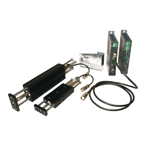
Typical servo system B1100-XX-YY: Servo controller motor and power supply.
NTI AG / inMot®www. inMot.com Page 5/19
B1100 Installation Guide

inMot Installation Guide
3 B1100 Interfaces
B1100-PP-XX
B1100-VF-XX
B1100-GP-XX
Connector
X1 Motor Supply ● ● ●
X2 Motor Phases (Screw Terminals) ● ● ●
X3 Motor / Motor Signals ● ● ●
X5 Com / Config RS232 RS485 CAN ● ● ●
X7 RS485 / CAN In ● ● ●
X8 RS485 / CAN Out ● ● ●
X13 External/Simulated Position Encoder
Diff Hall Switches ● ● ●
X14 6 Digital Inputs
6 Digital Outputs
Analog In 0..10V
Analog In –10V.. +10V
Diff Step Dir zero
24V Logic Supply
● ● ●
LED State Indicator ● ● ●
S4 Bus Termination ● ● ●
NTI AG / inMot®www. inMot.com Page 6/19
B1100 Installation Guide

inMot Installation Guide
4 Functionality
B1100-PP
B1100-PP-HC
B1100-PP-XC
B1100-VF
B1100-VF-HC
B1100-VF-XC
B1100-GP
B1100-GP-HC
B1100-GP-XC
Supply Voltage
Motor Supply 72VDC (24...85VDC) ● ● ● ● ● ● ● ● ●
Logic Supply 24VDC (22...26VDC) ● ● ● ● ● ● ● ● ●
Motor Phase Current
8A peak / 6A rms ● ● ●
15A peak / 9A rms ● ● ●
25A peak / 12A rms ● ● ●
Controllable Motors
LinMot P01-23x… ● ● ● ● ● ● ● ● ●
P01-37x… ● ● ● ● ● ● ● ● ●
P01-48x… ● ● ● ● ● ● ● ● ●
DC Motors ● ● ● ● ● ● ● ● ●
Brushless DC / EC Motors ● ● ● ● ● ● ● ● ●
Command Interface
Easy Steps Max. 6 Commands ● ● ● ● ● ● ● ● ●
+/-10V Current Command Interface ● ● ● ● ● ●
Step Direction Indexer Interface ● ● ● ● ● ●
Cmd Tab IO Interface (X14-IOs)
(with EasySteps) ● ● ● ● ● ●
RS232 up to 115.2 kBaud ● ● ●
RS485 up to 115.2 kBaud ● ● ●
CANOpen up to 1MBaud ● ● ●
DeviceNet 125 250 500 kBaud ● ● ●
External Position Sensor
Incremental RS422 up to 2 MHz ● ● ● ● ● ● ● ● ●
Position Indexer Input
Step Dir Zero/ ABZ RS422 up to 2 MHz ● ● ● ● ● ●
Position Encoder Simulation
AB RS422 up to 2.5 MHz ● ● ● ● ● ●
Configuration
RS232 Configuration ● ● ● ● ● ● ● ● ●
CAN Multi Axes Configuration ● ● ● ● ● ● ● ● ●
5 Soft are
The configuration software LinMot-Talk is free of charge and can be downloaded
from the LinMot homepage.
For fast results see also the quick start guides and configurations for the B1100-PP
and B1100-VF controllers:
•QuickStartGuide_B1100-PP.pdf
•QuickStartGuide_B1100-VF.pdf
This quick start guides are distributed with the LinMot-Talk software.
NTI AG / inMot®www. inMot.com Page 7/19
B1100 Installation Guide

inMot Installation Guide
6 Po er Supply and Grounding
In order to assure a safe and error free operation and to avoid severe damage
to system components all system components* must be well grounded to
either a single earth or utility ground. This includes both LinMot and all other
control system components to the same ground bus.
Each system component* should be tied directly to the ground bus (star
pattern) rather than daisy chaining from component to component. (LinMot
motors are properly grounded through their power cables when connected to
LinMot controllers.)
Po er supply connectors must not be connected or disconnected hile
DC voltage is present. Do not disconnect system components until all LinMot
controllers LEDs have turned off. (Capacitors in the power supply may not fully
discharge for several minutes after input voltage has been disconnected).
Failure to observe these precautions may result in severe damage to
electronic components in LinMot motors and/or controllers.
Do not s itch Po er Supply DC Voltage. All power supply switching and E-
Stop breaks should be done to the AC supply voltage of the power supply.
Failure to observe these precautions may result in severe damage to
controller.
* Inside of the B1100 controller the PWR motor GND and PWR signal GND is connected together and to the GND of the
controller housing. It is recommended that the PWR motor GND is NOT grounded at another place than inside of the
controller to avoid circular currents.
NTI AG / inMot®www. inMot.com Page 8/19
B1100 Installation Guide

inMot Installation Guide
7 Description of the connectors / Interfaces
7.1 X1
X1 Motor Supply
Screw Terminals Motor Supply: 72VDC nominal 24...85VDC
Absolute max. Rating: 72VDC +20%.
External Fuse: 10AT for LC (8Apeak) 16AT for HC and XC (15A/25Apeak) servos.
If motor supply voltage exceeds 90VDC the controller will go into error state.
- Tightening Torque: min 0.4Nm
- Screw Thread: M 2 5
- Use 60/75°C copper conductors only
- Conductor Cross-Section 2.5mm2 (AWG14) max Length 4m
7.2 X2
X2 Motor Phases
PH1+ /U
PH1- /V
PH2+ /W
PH2-
SCRN
LinMot Motor: 3-phase EC-Motor:
Motor Phase 1+ red Motor Phase U
Motor Phase 1- pink Motor Phase V
Motor Phase 2+ blue Motor Phase W
Motor Phase 2- grey
Shield
Screw Terminals The motor phases are present at X2 and X3. It is recommended to use X2. It is only allowed to use X3 for
connecting motor phases if RMS current is below 2A and peak current is below 4A.
Never connect motor phases on X2 and X3!
- Tightening Torque: min 0.4Nm
- Screw Thread: M 2 5
- Conductor Cross-: max. 2.5mm2 (AWG14) Length < 30m
- Use 60/75°C copper conductors only
NTI AG / inMot®www. inMot.com Page 9/19
B1100 Installation Guide

inMot Installation Guide
7.3 X3
X3 Motor
1
2
3
4
5
6
7
8
9
case
LinMot Motor: 3-phase EC-Motor:
Motor Phase 1+
Motor Phase 2+
+5VDC +5VDC (Hall Supply)
Sensor Sine Hall 1
Temp. In Hall 3
Motor Phase 1-
Motor Phase 2-
AGND AGND (Hall Supply)
Sensor Cosine Hall 2
Shield
DSUB-9 (f) Note:
Use +5V (X3.3) and AGND (X3.8) only for motor internal hall sensor supply (max. 100mA). Cable length <
30m.
Caution:
Do NOT connect AGND (X3.8) to ground or earth!
It is only allowed to use X3 for connecting the motor phases if RMS current is below 2A and peak current
below 4A.
Motor Wiring for Phase Currents above 2A RMS or 4A peak (recommended general iring)
Important:
If motor phase current exceeds 2ARMS or 4Apeak, motor phases must be ired to X2!
NTI AG / inMot®www. inMot.com Page 10/19
B1100 Installation Guide
Autres manuels pour B1100-PP
3
Ce manuel convient aux modèles suivants
4
Table des matières
Autres manuels LinMot Contrôleurs

LinMot
LinMot C1250-PD-XC-0S/1S Manuel utilisateur

LinMot
LinMot Series E1400-GP Manuel utilisateur

LinMot
LinMot E1250-PL Series Manuel utilisateur

LinMot
LinMot B1100-PP Manuel utilisateur

LinMot
LinMot E100 Series Manuel utilisateur
LinMot
LinMot E1200-GP-UC Mode d’emploi

LinMot
LinMot E1100-MP Manuel utilisateur

LinMot
LinMot E1100-CO Mode d’emploi

LinMot
LinMot E1200-GP-UC Manuel utilisateur

LinMot
LinMot E1250-EC-UC Manuel utilisateur


