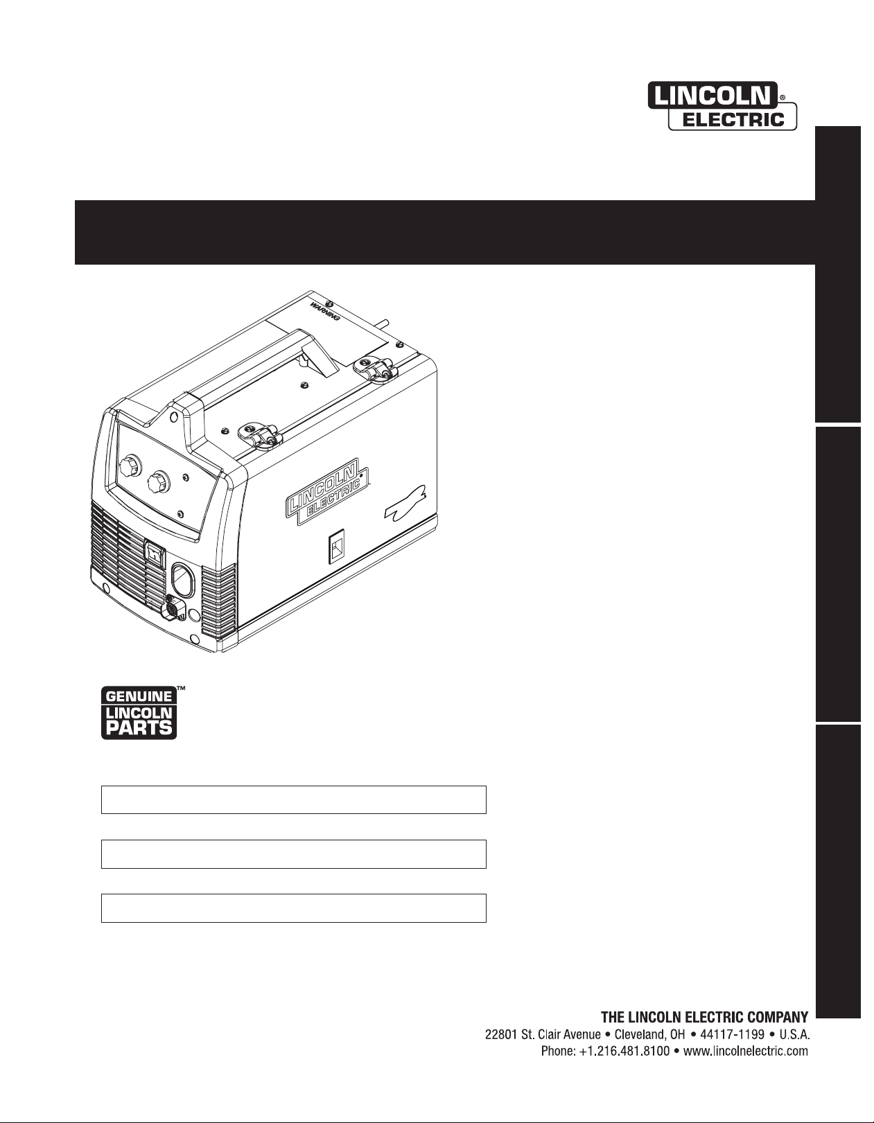
Linkoln Electric K2479-1 Manuel utilisateur

Operator’s Manua
WIRE FEEDER WELDERS (125, 140 MODELS)
Register your machine:
www.lin olnele tri . om/register
Authorized Service and Distributor Locator:
www.lin olnele tri . om/lo ator
IM10049-A | Issue D ate Mar- 14
© Lin oln Global, In . All Rights Reserved.
For use with ma hines having Code Numbers:
11631, 11632, 11633, 11634,
11635, 11636, 11637, 11638,
11639, 12100, 12101, 12102,
12103, 12104, 12105, 12106,
12107
Save for future reference
Date Pur hased
Code: (ex: 10859)
Serial: (ex: U1060512345)

THANK YOU FOR SE ECTING
A QUA ITY PRODUCT BY
INCO N E EC TRIC.
When this equipment is shipped, title passes to the purchaser upon
receipt by the carrier. Consequently, Claims for material damaged in
shipment must be made by the purchaser against the transportation
company at the time the shipment is received.
Lincoln arc welding and cutting equipment is designed and built with
safety in mind. However, your overall safety can be increased by
proper installation ... and thoughtful operation on your part.
DO NOT INSTALL, OPERATE OR REPAIR THIS EQUIPMENT
WITHOUT READING THIS MANUAL AND THE SAFETY PRECAUTIONS
CONTAINED THROUGHOUT. And, most importantly, think before you
act and be careful.
This statement appears where the information must be followed
exactly to avoid serious personal injury or loss of life.
This statement appears where the information must be followed to
avoid minor personal injury or damage to this equipment.
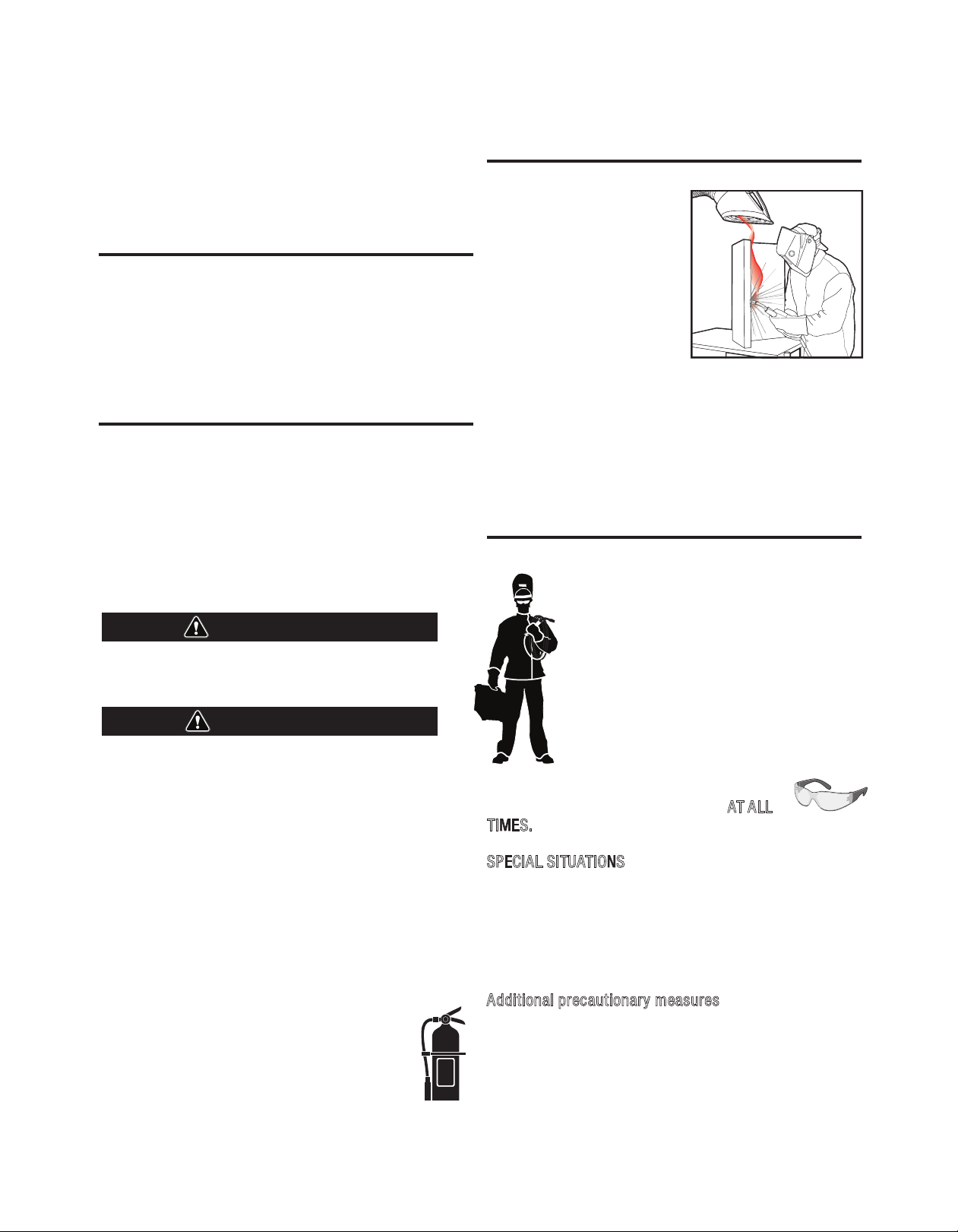
get too close to the arc. Use
corrective lenses if necessary to
stay a reasonable distance away
from the arc.
and obey the Material Safety
Data Sheet (MSDS) and the warning
label that appears on all containers
of welding materials.
or
exhaust at the arc, or both, to keep
the fumes and gases from your breathing zone and the general area.
, natural ventilation may be
adequate if you keep your head out of the fumes (See below).
or fans to keep the fumes away from your
face.
If you de velop unusual symptoms, see your supervisor. Perhaps the
welding atmosphere and ventilation system should be checked.
your eyes and face with welding helmet
properly fitted and with proper grade of filter plate
(See ANSI Z49.1).
your body from welding spatter and arc
flash with protective clothing including woolen
clothing, flame-proof apron and gloves, leather
leggings, and high boots.
others from splatter, flash, and glare with
protective screens or barriers.
, protection from noise may be
appropriate.
protective equipment is in good condition.
Also, wear safety glasses in work area AT ALL
TIMES.
SPECIAL SITUATIONS
containers or materials which previously had
been in contact with hazardous substances unless they are properly
cleaned. This is extremely dangerous.
painted or plated parts unless special
precautions with ventilation have been taken. They can release highly
toxic fumes or gases.
Additional precautionary measures
compressed gas cylinders from excessive heat, mechanical
shocks, and arcs; fasten cylinders so they cannot fall.
cylinders are never grounded or part of an electrical circuit.
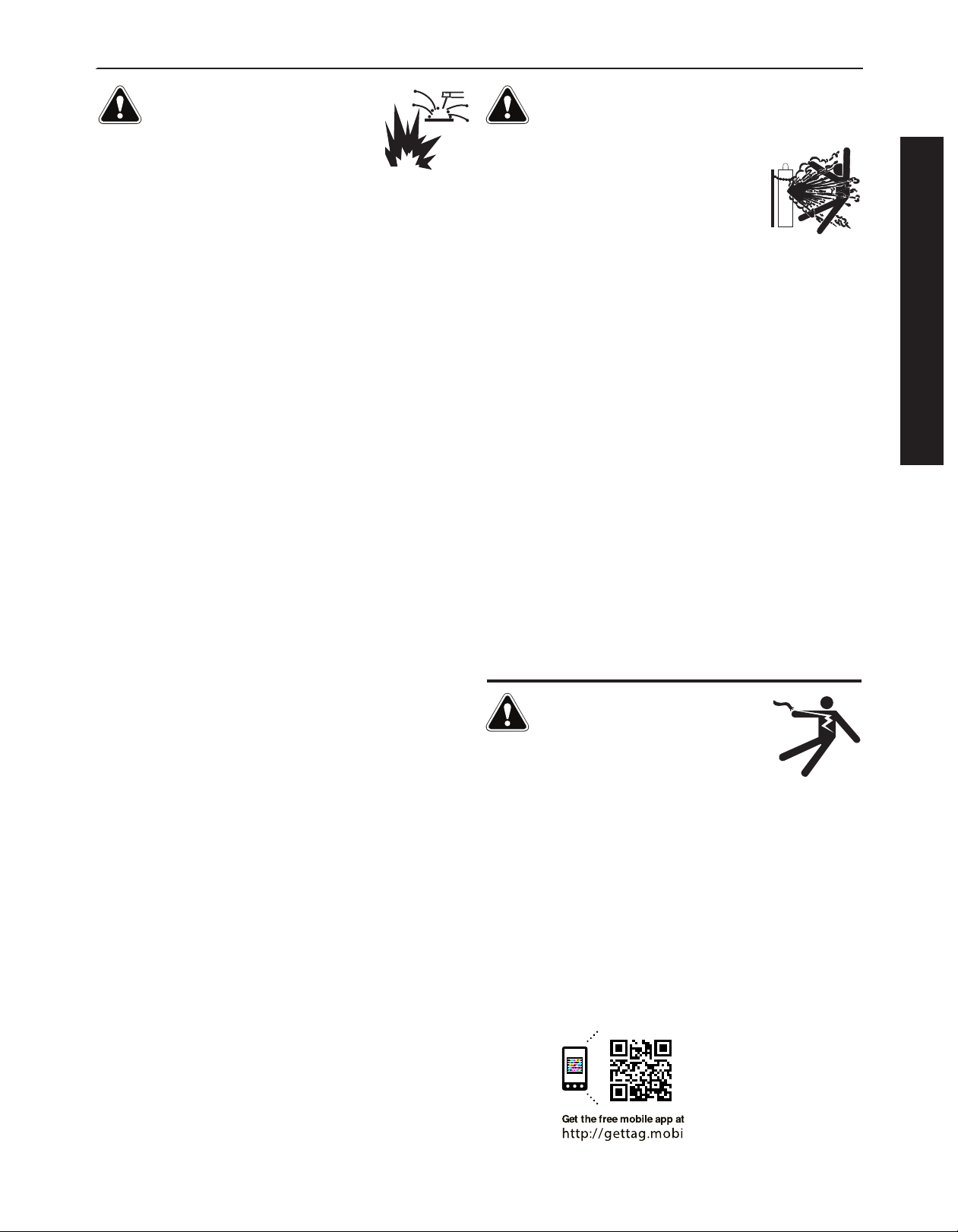
all potential fire hazards from welding area.
WARNING
CAUTION

SECTION A:
WARNINGS
CA IFORNIA PROPOSITION 65 WARNINGS
Diesel Engines
Diesel engine exhaust and some of its constituents are known
to the State of California to cause cancer, birth defects, and other
reproductive harm.
Gasoline Engines
The engine exhaust from this product contains chemicals known
to the State of California to cause cancer, birth defects, or other
reproductive harm.
Read and understand the following safety highlights. or additional
safety information, it is strongly recommended that you purchase a
copy of “Safety in Welding & Cutting - ANSI Standard Z49.1” from the
American Welding Society, P.O. Box 351040, Miami, lorida 33135 or
CSA Standard W117.2-1974. A ree copy of “Arc Welding Safety”
booklet E205 is available from the Lincoln Electric Company, 22801
St. Clair Avenue, Cleveland, Ohio 44117-1199.
BE SURE THAT ALL INSTALLATION, OPERATION,
MAINTENANCE AND REPAIR PROCEDURES ARE
PERFORMED ONLY BY QUALIFIED INDIVIDUALS.
FOR ENGINE POWERED
EQUIPMENT.
1.a. Turn the engine off before troubleshooting
and maintenance work unless the
maintenance work requires it to be running.
1.b. Operate engines in open, well-ventilated
areas or vent the engine exhaust fumes outdoors.
1.c. Do not add the fuel near an open flame
welding arc or when the engine is running.
Stop the engine and allow it to cool before
refueling to prevent spilled fuel from
vaporizing on contact with hot engine parts
and igniting. Do not spill fuel when filling
tank. If fuel is spilled, wipe it up and do not start engine until
fumes have been eliminated.
1.d. Keep all equipment safety guards, covers and
devices in position and in good repair.Keep
hands, hair, clothing and tools away from
V-belts, gears, fans and all other moving parts
when starting, operating or repairing
equipment.
1.e. In some cases it may be necessary to remove safety guards to
perform required maintenance. Remove guards only when
necessary and replace them when the maintenance requiring
their removal is complete. Always use the greatest care when
working near moving parts.
1.f. Do not put your hands near the engine fan. Do not attempt to
override the governor or idler by pushing on the throttle control
rods while the engine is running.
1.g. To prevent accidentally starting gasoline engines while turning
the engine or welding generator during maintenance work,
disconnect the spark plug wires, distributor cap or magneto wire
as appropriate.
1.h. To avoid scalding, do not remove the radiator
pressure cap when the engine is hot.
E ECTRIC AND
MAGNETIC FIE DS MAY
BE DANGEROUS
2.a. Electric current flowing through any conductor
causes localized Electric and Magnetic ields (EM ). Welding
current creates EM fields around welding cables and welding
machines
2.b. EM fields may interfere with some pacemakers, and welders
having a pacemaker should consult their physician before
welding.
2.c. Exposure to EM fields in welding may have other health effects
which are now not known.
2.d. All welders should use the following procedures in order to
minimize exposure to EM fields from the welding circuit:
2.d.1. Route the electrode and work cables together - Secure
them with tape when possible.
2.d.2. Never coil the electrode lead around your body.
2.d.3. Do not place your body between the electrode and work
cables. If the electrode cable is on your right side, the
work cable should also be on your right side.
2.d.4. Connect the work cable to the workpiece as close as pos-
sible to the area being welded.
2.d.5. Do not work next to welding power source.
SAFETY
OPERATOR’S MANUA

E ECTRIC SHOCK
CAN KI .
3.a. The electrode and work (or ground) circuits are
electrically “hot” when the welder is on. Do
not touch these “hot” parts with your bare skin
or wet clothing. Wear dry, hole-free gloves to insulate hands.
3.b. Insulate yourself from work and ground using dry insulation.
Make certain the insulation is large enough to cover your full area
of physical contact with work and ground.
• Semiautomatic DC Constant Voltage (Wire) Welder.
• DC Manual (Stick) Welder.
• AC Welder with Reduced Voltage Control.
3.c. In semiautomatic or automatic wire welding, the electrode,
electrode reel, welding head, nozzle or semiautomatic welding
gun are also electrically “hot”.
3.d. Always be sure the work cable makes a good electrical
connection with the metal being welded. The connection should
be as close as possible to the area being welded.
3.e. Ground the work or metal to be welded to a good electrical (earth)
ground.
3.f. Maintain the electrode holder, work clamp, welding cable and
welding machine in good, safe operating condition. Replace
damaged insulation.
3.g. Never dip the electrode in water for cooling.
3.h. Never simultaneously touch electrically “hot” parts of electrode
holders connected to two welders because voltage
between the
two can be the total of the open circuit voltage of both
welders.
3.i. When working above floor level, use a safety belt to protect
yourself from a fall should you get a shock.
3.j. Also see It ems 6.c. and 8.
ARC RAYS CAN BURN.
4.a. Use a shield with the proper filter and cover plates to protect your
eyes from sparks and the rays of the arc when welding or
observing open arc welding. Headshield and filter lens should
conform to ANSI Z87. I standards.
4.b. Use suitable clothing made from durable flame-resistant material
to protect your skin and that of your helpers from the arc rays.
4.c. Protect other nearby personnel with suitable, non-flammable
screening and/or warn them not to watch the arc nor expose
themselves to the arc rays or to hot spatter or metal.
FUMES AND GASES
CAN BE DANGEROUS.
5.a. Welding may produce fumes and gases
hazardous to health. Avoid breathing these
fumes and gases. When welding, keep your head out of the fume.
Use enough ventilation and/or exhaust at the arc to keep fumes
and gases away from the breathing zone.
5. b. The operation of welding fume control equipment is affected by
various factors including proper use and positioning of the
equipment, maintenance of the equipment and the specific
welding procedure and application involved. Worker exposure
level should be checked upon installation and periodically
thereafter to be certain it is within applicable OSHA PEL and
ACGIH TLV limits.
5.c. Do not weld in locations near chlorinated hydrocarbon vapors
coming from degreasing, cleaning or spraying operations. The
heat and rays of the arc can react with solvent vapors to form
phosgene, a highly toxic gas, and other irritating products.
5.d. Shielding gases used for arc welding can displace air and
cause
injury or death. Always use enough ventilation, especially in
confined areas, to insure breathing air is safe.
5.e. Read and understand the manufacturer’s instructions for this
equipment and the consumables to be used, including the
material safety data sheet (MSDS) and follow your employer’s
safety practices. MSDS forms are available from your welding
distributor or from the manufacturer.
5.f. Also see item 1.b.
SAFETY

WE DING AND CUTTING
SPARKS CAN CAUSE
FIRE OR EXP OSION.
6.a. Remove fire hazards from the welding area. If
this is not possible, cover them to prevent the
welding sparks from starting a fire. Remember that welding
sparks and hot materials from welding can easily go through
small cracks and openings to adjacent areas. Avoid welding near
hydraulic lines. Have a fire extinguisher readily available.
6.b. Where compressed gases are to be used at the job site, special
precautions should be used to prevent hazardous situations.
Refer to “Safety in Welding and Cutting” (ANSI Standard Z49.1)
and the operating information for the equipment being used.
6.c. When not welding, make certain no part of the electrode circuit is
touching the work or ground. Accidental contact can cause
overheating and create a fire hazard.
6.d. Do not heat, cut or weld tanks, drums or containers until the
proper steps have been taken to insure that such procedures will
not cause flammable or toxic vapors from substances inside.
They can cause an explosion even though they have been
“cleaned”. or information, purchase “Recommended Safe
Practices for the Preparation for Welding and Cutting of
Containers and Piping That Have Held Hazardous Substances”,
AWS 4.1 from the American Welding Society (see address
above).
6.e. Vent hollow castings or containers before heating, cutting or
welding. They may explode.
6.f. Sparks and spatter are thrown from the welding arc. Wear oil free
protective garments such as leather gloves, heavy shirt, cuffless
trousers, high shoes and a cap over your hair. Wear ear plugs
when welding out of position or in confined places. Always wear
safety glasses with side shields when in a welding area.
6.g. Connect the work cable to the work as close to the welding area
as practical. Work cables connected to the building framework or
other locations away from the welding area increase the
possibility of the welding current passing through lifting chains,
crane cables or other alternate circuits. This can create fire
hazards or overheat lifting chains or cables until they fail.
6.h. Also see item 1.c.
6.I. Read and follow N PA 51B “ Standard for ire Prevention During
Welding, Cutting and Other Hot Work”, available from N PA, 1
Batterymarch Park, PO box 9101, Quincy, Ma 022690-9101.
6.j. Do not use a welding power source for pipe thawing.
CY INDER MAY EXP ODE IF
DAMAGED.
7.a. Use only compressed gas cylinders containing
the correct shielding gas for the process used
and properly operating regulators designed for
the gas and pressure used. All hoses, fittings,
etc. should be suitable for the application and
maintained in good condition.
7.b. Always keep cylinders in an upright position securely chained to
an undercarriage or fixed support.
7.c. Cylinders should be located:
• Away from areas where they may be struck or subjected
to physical damage.
• A safe distance from arc welding or cutting operations
and any other source of heat, sparks, or flame.
7.d. Never allow the electrode, electrode holder or any other
electrically “hot” parts to touch a cylinder.
7.e. Keep your head and face away from the cylinder valve outlet
when opening the cylinder valve.
7.f. Valve protection caps should always be in place and hand tight
except when the cylinder is in use or connected for use.
7.g. Read and follow the instructions on compressed gas cylinders,
associated equipment, and CGA publication P-l, “Precautions for
Safe Handling of Compressed Gases in
Cylinders,” available
from the Compressed Gas Association 1235 Jefferson Davis
Highway, Arlington, VA 22202.
FOR E ECTRICA Y
POWERED EQUIPMENT.
8.a. Turn off input power using the disconnect
switch at the fuse box before working on the
equipment.
8.b. Install equipment in accordance with the U.S. National Electrical
Code, all local codes and the manufacturer’s recommendations.
8.c. Ground the equipment in accordance with the U.S. National
Electrical Code and the manufacturer’s recommendations.
SAFETY
Weld ng Safety
Interact ve Web Gu de
for mob le dev ces
OPERATOR’S MANUA

TABLE OF CONTENTS
TAB E OF CONTENTS
General Decription. . . . . . . . . . . . . . . . . . . . . . Page 7
Installation . . . . . . . . . . . . . . . . . . . . . . . . .Section A
Technical Specifications . . . . . . . . . . . . . . . . . . . . .A-1
Identify and Locate Components for 125 Amp Unit .A-2
Identify and Locate Components for 140 Amp Unit .A-3
Operation . . . . . . . . . . . . . . . . . . . . . . . . . . .Section B
Safety and Product Description . . . . . . . . . . . . . . . .B-1
Controls and Settings . . . . . . . . . . . . . . . . . . .B-2, B-3
Dual Track Drive Roll and Wire Guide Table . . . . . .B-4
Setting Up and Making a lux-Cored Weld with a 125Amp
or 140Amp machines . . . . . . . . . . . . . . . . .B-4 thru B-6
Setting Up and Making a MIG Weld and Install Shielding
Gas for a 140Amp machine . . . . . . . . . .B-7 thru B-10
Setting Up and Making a Aluminum Weld . . . . . . .B-11
Accessories . . . . . . . . . . . . . . . . . . . . . . . . .Section C
Optional Accessories . . . . . . . . . . . . . . . . . . . . . . .C-1
Utility Carts . . . . . . . . . . . . . . . . . . . . . . . . . . .C-2, C-3
Maintenance . . . . . . . . . . . . . . . . . . . . . . . .Section D
Safety Precautions . . . . . . . . . . . . . . . . . . . . . . . . .D-1
Wire eed Compartment, an Motor, Wire Reel
Maintenance . . . . . . . . . . . . . . . . . . . . . . . . . . . . .D-1
Gun And Cable Maintenance . . . . . . . . . . . . . . . . . .D-2
Overload Protection . . . . . . . . . . . . . . . . . . . . . . . .D-2
Component Replacement Procedures . . . . . . . . . . .D-2
Troubleshooting . . . . . . . . . . . . . . . . . . . . .Section E
Safety Precautions . . . . . . . . . . . . . . . . . . . . . . . . .E-1
How to Use Troubleshooting Guide . . . . . . . . . . . . .E-1
Troubleshooting Guide . . . . . . . . . . . . . . .E-2 thru E-3
Wiring Diagram and Dimension Print . . . . . . . . . Section F
Parts Pages . . . . . . . . . . . . . . . . . . . .P-653, P-202-E

PRODUCT DESCRIPTION
PRODUCT DESCRIPTION (PRODUCT CAPABI ITIES)
The portable 125Amp Wire eeder Model is capable of flux-cored
welding on mild steel. The portable 140Amp Wire eeder Model is
capable of MIG welding on steel, stainless steel, and aluminum, in
addition to flux-core welding on mild steel.
MIG welding stands for Metal Inert Gas welding and requires a
separate bottle of shielding gas to protect the weld. The Shielding
gas used is determined by the type of material you are welding on.
Shielding gases can be purchased separately from your local
welding gas distributor. MIG welding is ideal for welding on thin
and clean materials when an excellent cosmetic weld is required.
An example is automotive body panels.
CAW-S stands for Self shielding lux-cored Arc Welding and does
not require a shielding gas to protect the weld since the welding
wire has special additives known as flux to protect the weld from
impurities. lux-cored welding is ideal for medium to thicker
material and for welding on painted or rusty steel. lux-cored
welding is also ideal for outdoor applications where windy condi-
tions might blow the MIG shielding gas away from the weld. lux-
cored welding produces a good looking weld but does not produce
an excellent weld appearance as MIG welding does.
Your 140Amp machine includes the necessary items to weld with
either the flux-cored welding or MIG welding process on steel. To
weld on stainless steel, an optional stainless steel welding wire
can be purchased separately. The 140Amp machine is spool gun
ready and the machine can weld aluminum using .035”(0.9mm)
diameter 4043 aluminum welding wire. Since aluminum welding
wire is soft, an optional spool gun is recommended for best
results. A welding Procedure Decal on the wire drive compartment
door provides suggested settings for welding.
COMMON WE DING ABBREVIATIONS
GMAW (MIG)
• Gas Metal Arc Welding
FCAW (Innershield or Outershield)
• lux Core Arc Welding
WIRE FEEDER WELDERS (125, 140)
OPERATOR’S MANUA

INSTALLATIONWIRE FEEDER WELDERS (125, 140)
TECHNICA SPECIFICATIONS
125 Amp units (K2479-1, K2513-1, K2696-1, K2699-1, K2785-1)
140 Amp units (K2480-1, K2514-1, K2658-1, K2697-1)
1If connected to a circuit protected by fuses use Time Delay use marked “D”.
2Requirements For Maximum Output
In order to utilize the maximum output capability of the machine, a branch circuit capable
of 25 amps at 120 volts, 60 Hertz is required.
INPUT – SING E PHASE ON Y
RATED OUTPUT
OUTPUT
Standard Voltage/Frequency
120 V / 60 Hz
Duty Cycle
20% Duty Cycle
Current
90 Amps
Voltage at Rated Amperes
19
Welding Current Range
30-125 Amps
Input Voltage / Frequence
120V 60Hz
Height
13.7 in.
347 mm
Width
10.15 in.
258 mm
Depth
17.9 in.
454 mm
Weight
49.5 lbs.
22.5 kg.
Fuse or Breaker Size1,2
20 Amp
Input Amps
20
Power Cord
15 Amp, 125 V,
Three Prong Plug
(NEMA Type 5-15P)
Extension Cord
3 Conductor # 12 AWG
(4mm2) or Larger
up to 50 ft.(15.2m)
Maximum-Open Circuit Voltage
33 V
Wire Speed Range
50 - 500 in/min.
(1.3 - 12.7 m/min.)
Input Current
20 Amps @ rated output
RECOMMENDED INPUT CAB E AND FUSE SIZES
PHYSICA DIMENSIONS
INPUT – SING E PHASE ON Y
RATED OUTPUT
OUTPUT
Standard Voltage/Frequency
120 V / 60 Hz
Duty Cycle
20% Duty Cycle
Current
90 Amps
Voltage at Rated Amperes
19.5
Welding Current Range
30-140 Amps
Input Voltage / Frequence
120V 60Hz
Height
13.7 in.
347 mm
Width
10.15 in.
258 mm
Depth
17.9 in.
454 mm
Weight
49.5 lbs.
22.5 kg.
Fuse or Breaker Size1,2
20 Amp
Input Amps
20
Power Cord
15 Amp, 125 V,
Three Prong Plug
(NEMA Type 5-15P)
Extension Cord
3 Conductor # 12 AWG
(4mm2) or Larger
up to 50 ft.(15.2m)
Maximum-Open Circuit Voltage
33 V
Wire Speed Range
50 - 500 in/min.
(1.3 - 12.7 m/min.)
Input Current
20 Amps @ rated output
RECOMMENDED INPUT CAB E AND FUSE SIZES
PHYSICA DIMENSIONS

INSTALLATIONWIRE FEEDER WELDERS (125, 140)
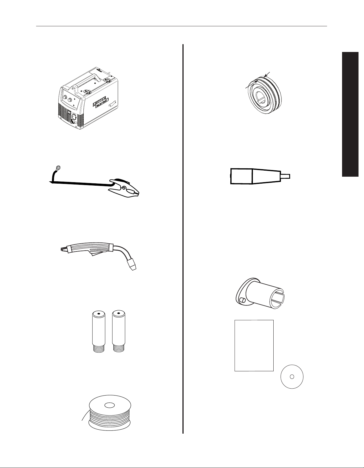
• .025” -.035”(0.6mm-0.8mm) Dual Groove Drive Roll
( actory installed .035”(0.9mm) groove ready for flux-
cored process)
• Black Gun Nozzle (Installed on Welding Gun)
• 2”(51mm) Spindle Adapter ( or 8”
(203mm) reel of wire)
• Instruction Manual
• How to Weld “DVD”
• Wire eeder Welder
• Work Cable & Clamp
• Magnum 100L Welding Gun
• (3) .035”(0.9mm) Contact Tips (1 installed on the welding gun)
• Spool of .035”(0.9mm) diameter NR-211MP Innershield lux-
cored Wire
IDENTIFY AND OCATE COMPONENTS for 125 AMP UNIT
.035
.035
.035 NR-211 MP
F
L
U
X
-
C
O
R
E
D
W
I
R
E
.
0
2
5
.025 GROOVE
.035 GROOVE
IM
"INSTRUCTION
MANUAL"
DVD
2" SPINDLE ADAPTER (FOR 8" REEL OF WIRE)
OPERATOR’S MANUA

INSTALLATIONWIRE FEEDER WELDERS (125, 140)
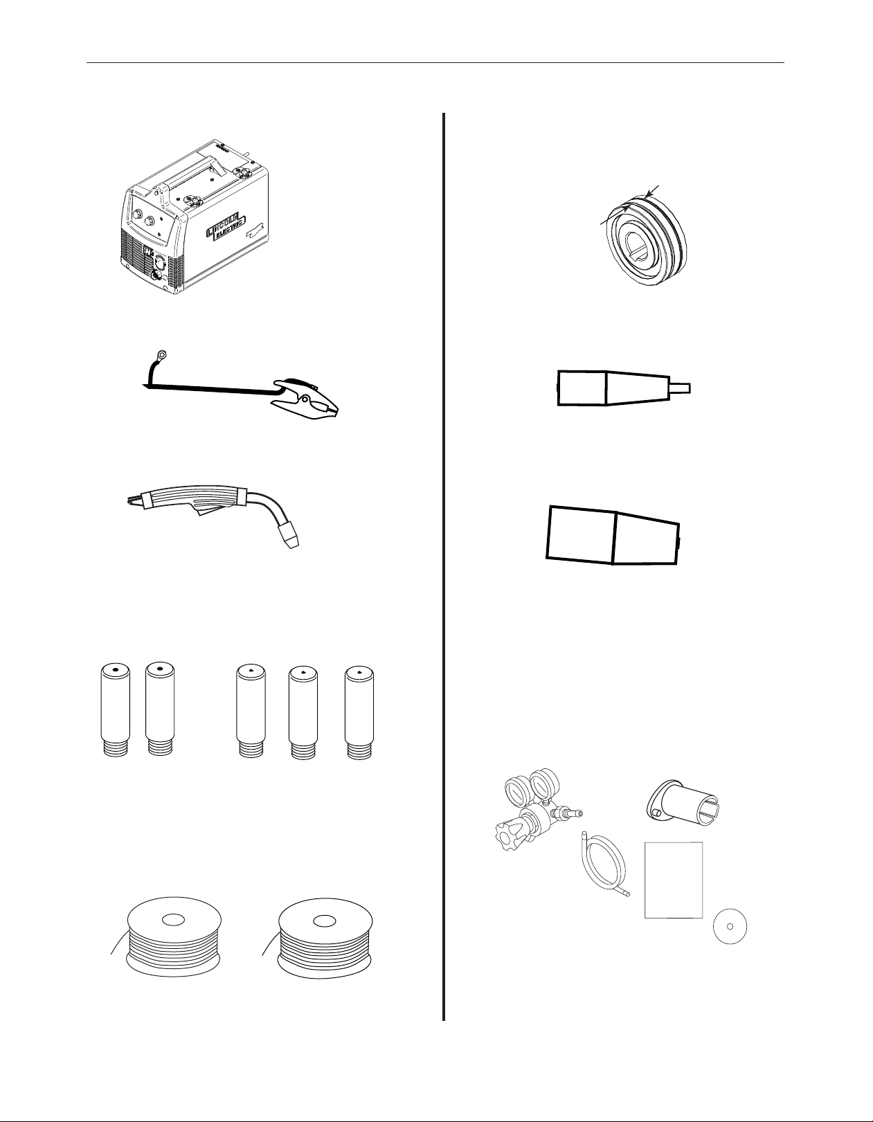
• Wire eeder Welder
• Work Cable & Clamp
• Magnum 100L Welding Gun
• (3) .035”(0.9mm) Contact Tips (1 installed on the welding gun).
• (3) .025”(0.6mm) Contact Tips
• Spool of .035”(0.9mm) diameter NR-211MP
Innershield lux-cored Wire
• Spool of .025”(0.6mm) diameter Super Arc L-56 MIG Wire
• .025” -.035”(0.6mm-0.8mm) Dual Groove Drive Roll
( actory installed .035”(0.9mm) groove ready for
flux-cored process).
• Black Gun Nozzle (Installed on Welding Gun)
• Brass MIG Gun Nozzle for MIG welding
• 2”(51mm) Spindle Adapter for 8”(203mm) reel of
wire.
• Regulator
• Gas Hose
• Instruction Manual
• How to Weld “DVD”
.025
.025
.025
.035
.035
NR-211 MP
WIRE
L-56 MIG
NR-211 MP
WIRE
L-56 MIG
IM10049
"INSTRUCTION
MANUAL"
DVD
GAS HOSE
REGULATOR
2" SPINDLE ADAPTER (FOR 8" REEL OF WIRE)
IDENTIFY AND OCATE COMPONENTS for 140 AMP UNIT
.
0
2
5
.025 GROOVE
.035 GROOVE
Ce manuel convient aux modèles suivants
8
Table des matières
Langues :
Manuels Système de soudage populaires d'autres marques

TAFA
TAFA 30*8B35 Manuel utilisateur

Lincoln Electric
Lincoln Electric INVERTEC V350-PRO CE Manuel utilisateur

ESAB
ESAB Buddy Arc 145 Manuel utilisateur

CIGWELD
CIGWELD 636804 Guide rapide

Red-D-Arc
Red-D-Arc DC-400 Manuel utilisateur

Hobart Welding Products
Hobart Welding Products Spool Gun DP 3035-10 Manuel utilisateur