Doc #: L-2600-1020 Page 7 Rev. 01
When using AC power, use the L1, L2 and PE
terminals. When using an external +24 VDC power
supply, use the +24, GND, and PE terminals. The
table at right shows the usage and specifications of
the connections on the power connector.
The Sensor Interface can be powered from EITHER 100-240VAC OR
+24VDC. Never hook up both AC and DC power at the same time.
When using an external +24 VDC supply, make sure the Power
Jumper (see Figure 3) is removed so that the internal +24 VDC supply
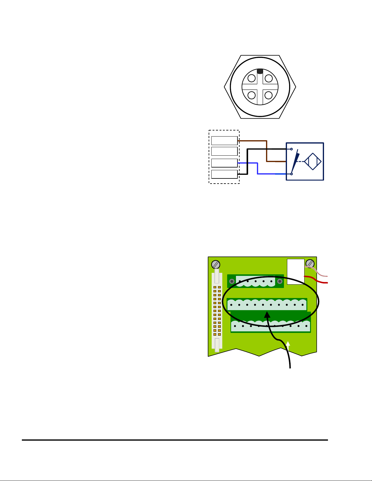
2.1.2 Internal Sensor Connector Wiring
The Internal Sensor Connector (see Figure
3) is primarily used in conjunction with a
Quick Connect bulkhead connector for
mass die termination or if there are some
sensors that are always present on the
machine regardless of what die is
installed. Link offers (Link PN 109090)
an optional quick connect bulkhead
connector (using a Turck CS-19
connector) that is prewired and ready to
plug into the Internal Sensor Connector.
Figure 4 at right shows how a typical
sensor is wired into this connector. The
unit is supplied with a blank plate for
mounting an existing connector if a
connector system is already in use.
Power Connector (See Figure 3)
90 – 264 VAC Line
29 VA (0.4 Amp at 90 VAC)
Protective Earth (used with both AC
and DC input power)
(Up to 10 Amps can be passed
NOTE: When using an externa +24 VDC
supply, the Power Jumper (see
Figure 3) must be removed. This
disconnects the internal +24 VDC
supply of the Sensor interface.
L1
L2
PE
+24
GND
O1
O2
O3
O4
O5
O6
O7
O8
NC
GND
I1
I2
I3
I4
I5
I6
I7
I8
+24
GND
Internal
Sensor
Connector
1
6
4
5
2
3
7
8
I1
I6
I4
I5
I2
I3
I7
I8
9
10
+24
GND
NPN
BN
BU
NPN
Proximity
Sensor
BK
Figure 4: Typical Wiring to Internal Sensor Connector
NOTE: If a Quick Connect bulk
connector is wired into this
connector but there are
inputs that are not actually
connected in the die, then
the corresponding front
panel connectors are still
available for use.