Lefflerpost RMC2ATEM Manuel utilisateur

RMC2ATEM USERS GUIDE Page 1
RMC2ATEM USERS GUIDE
Version 7
This document describes the datavideo
TM
RMC-260 control panel when used in conjunction with the
RMC2ATEM controller to control any ATEM production switcher.
INSTALLATION
The RMC-260 is normally delivered with a 12 volt 0.5 amp power adaptor and a 9 pin control cable.
The 9 pin control cable connects to the RMC2ATEM at the networ connection end (RMC panel 1).
The RMC2ATEM v1 is delivered with a USB cable (for firmware updates only.
The RMC2ATEM v2 is delivered with a USB cable (for firmware updates) and a 9 volt power cable which
connects the RMC-260 to the RMC2ATEM (9v OUT) to facilitate a single power connection for both units. The
optional Tally/GPI box and 7” touch screen control panel also uses this 9 volt power that is provided on their
respective connectors.
The 12 volt power adaptor that is included in the RMC-260 pac age does not have the capacity to run the
RMC-260 and the RMC2ATEM let alone the optional Tally/GPI box and 7” touch screen control panel. In fact
it barely gets by just powering the RMC-260. So it is recommended to purchase a power adaptor rated at 9
volt 2 amp and connect to the power in (9v IN) on the RMC2ATEM controller.
PLEASE NOTE:
The TERMINAL baud rate setting has changed from 115200 to 9600 due to some connections unable to
handle the data speed. This does not affect the functionality of the RMC2ATEM but you will need to select it
accordingly when establishing the TERMINAL connection with your computer.

RMC2ATEM USERS GUIDE Page 2
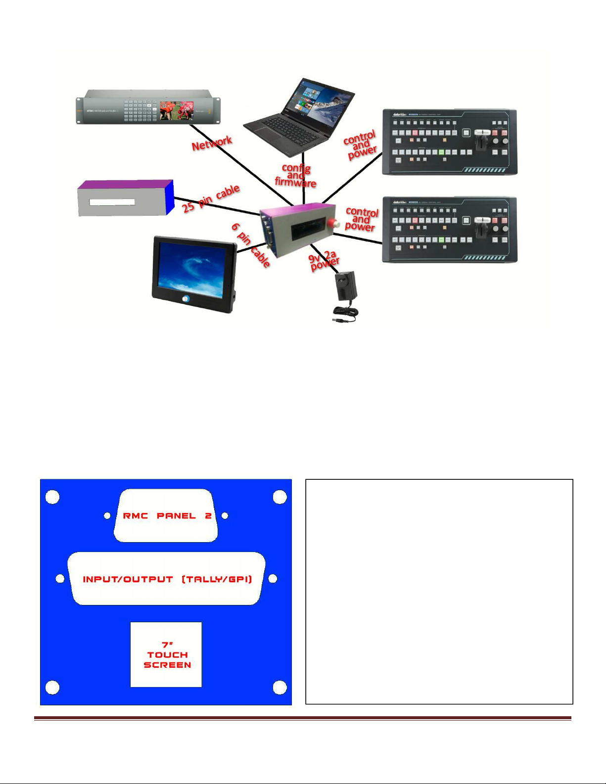
CONNECTION
The RMC2ATEM is the heart of all the interconnections.
Connection Version 1
The RMC2ATEM v1 supplies 9 volt power to the RMC-260 panel and receives 9 volt 2 amp power from a
power adaptor. It also has two way control interface to the RMC-260 panel. It can connect to the ATEM using
a single RJ45 CAT5 networ cable or it can connect into a networ router/switch where an ATEM is also
connected. The USB connector can connect to either a MAC or a PC and be used to setup all the internal
configutations of the RMC2ATEM as well as doing firmware upgrades. The RMC2ATEM can also be powered
from the USB connection but separate power will have to be supplied to the RMC-260.
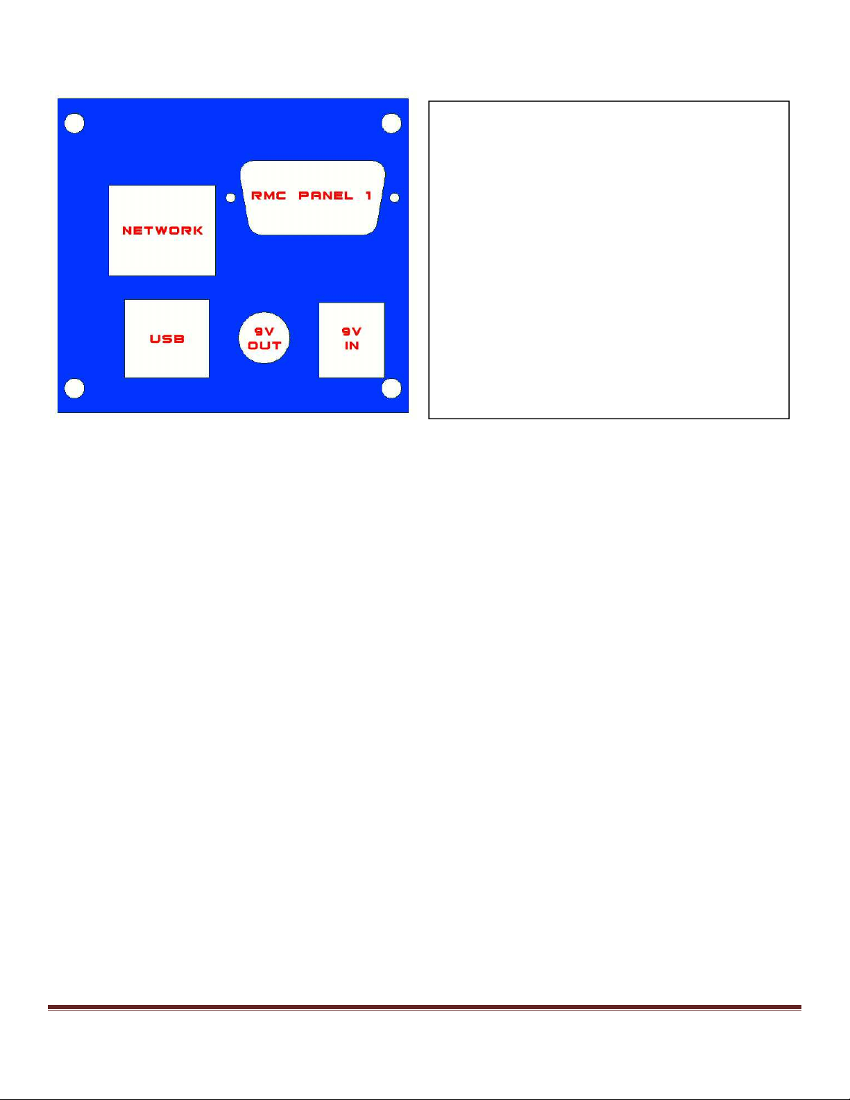
NETWORK/POWER PANEL
The only connection panel available on the
RMC2ATEM Version 1 has a network
connector, a USB connector, a v power in
and a pin D control connector for the
RMC-260 control panel.
There is also an optional INTERCONNECT
PANEL that can facilitate the TALLY/GPI
capabilities of the V2 model.
RMC2ATEM USERS GUIDE Page 3
Connection Version 2
The RMC2ATEM supplies 9 volt power to two RMC-260 panels, receives 9 volt 2 amp power from a power
adaptor, supplies 9 volt power to the optional 7” touch screen panel and tally/GPI box. It also has a two way
control interface to two RMC-260 panels. It can connect to the ATEM using a single RJ45 CAT5 networ cable
or it can connect into a networ router/switch where an ATEM is also connected. The USB connector can
connect to either a MAC or a PC and be used to setup all the internal configutations of the RMC2ATEM as well
as doing firmware upgrades. The RMC2ATEM can also be powered from the USB connection but separate
power will have to be supplied to the RMC-260.
INTERCONNECT PANEL
The interconnect panel on the RMC2ATEM
has the pin D control connector for the 2
nd
RMC-260 control panel, a 25 pin D
connector for the Tally and GPI functions
and a 6 pin Minidin connector for the
optional 7” touch screen (extended control).
The GPI functions can include multiple SHIFT
commands to alter the effect of some
button controls.
RMC2ATEM USERS GUIDE Page 4
The 9 pin and the 25 pin D connectors have hex screws attached to facilitate screw on plugs. DO NOT over
tighten these screws as they may unscrew the case screws when disconnecting. They should only be loosely
screwed in to prevent accidently falling out. The 7” touch screen connector and the Tally/GPI connectors have
9 volts on the to supply power for their electronics, so be careful not to cross connect them as it may cause
electronic component damage.
NETWORK/POWER PANEL
The network/power panel on the
RMC2ATEM has a network connector, a
USB connector, a v power in, a v power
out and a pin D control connector for the
main RMC-260 control panel.

RMC2ATEM USERS GUIDE Page 5
CONTROL COMPONENTS
The RMC2ATEM Version 1 does not have any control parts on the unit. It only has a tricoloured LED to indicate
certain conditions the controller is in.
All configurations are achieved using the USB port. These are described in more detail later.
The RMC2ATEM Version 2 besides having the tricoloured LED, also has a 16 character by 2 line alphanumeric
rear illuminated display along with a digital scroll control with push button switch. The nob on the scroll
control has 2 separate diameters to facillitate coarse and fine mechanical movement.
As an operational extra, you are able to program some of the pins on the 25 pin Tally/GPI connector to give you SHIFT
functions. As mentioned above, this can give you the ability to alter some of the RMC-26 button functions.
For example, using SHIFT 1 and the PROGRAM BUSS you can alter what source is selected. Pressing buttons 1 to 8 on
the program can select allocated inputs to buttons 1 to 8 and with the SHIFT 1 button pushed you can select a totally
different range of sources; basically giving you 16 switchable inputs. The same applies to the PREVIE BUSS.
Another example is using SHIFT 1 in conjunction with the PROGRAM BUSS DSK button. Without SHIFT 1, pressing the
program buss DSK will FADE ON or OFF the DSK, and using the SHIFT 1 with the DSK button will CUT ON and CUT OFF the
DSK.
**************************************************************************************************
Currently the SHIFT 1 FUNCTION is permanently attached to pin 17 of the Tally/GPI connector. This will be able to be
programmed to any pin in a future software release.
So to take advantage of using the SHIFT 1 function, connect a momentary switch between pin 17 and 25.
**************************************************************************************************

RMC2ATEM USERS GUIDE Page 6
RMC-260 CONTROL FUNCTIONS
The RMC-260 control panel was never designed specifically to control an ATEM. The RMC2ATEM controller converts the
logical layout of the RMC-260 to allow for the least amount of re-labelling and operation to be as logical as possible.
The following are the sections of the RMC-260 that are specific to the operation of an ATEM.
These are the PROGRAM and PREVIEW BUSSES. Each has 8 mapable input selectors and a STILL BUTTON for
invo ing the direct STILL transition and selections from the ATEM Media Players. The panel has specialised
labels for BLACK (BLK) and BACKGROUND (BKG) but they can be allocated to be any input besides blac and
bac ground. When used in conjunction with the LOGO button (SHIFT) an extra 8 inputs can be allocated.
When in STILL MODE any of these PROGRAM and PREVIEW buttons can be used to directly select any
available still into a media player and transition to and from other STILL and NON STILL inputs.
When an input selected on the ATEM is not allocated to any of the PROGRAM or PREVIEW buttons the lamps
on these buttons will rapidly flash left to right and bac to left again. (this is different from where the lamps
rapidly flash in one direction only which indicates loss of communications with the ATEM.
These are the USER 1 to USER 9 buttons used in conjunction with the USER SAVE button. To SAVE a panel
setup press USER SAVE and then a USER 1 to USER 9 button. To RECALL a panel setup press a USER 1 to
USER 9 button with the USER WIPE off. Panel setups contain all the configurations of the RMC-260 that
pertain to the ATEM including PROGRAM/PREVIEW crosspoint allocations, KEY and AUX crosspoint
allocations, Tally/GPI setups etc.

RMC2ATEM USERS GUIDE Page 7
When USER 1 to USER 6 are pressed in conjunction with USER WIPE they select 1 of 6 preallocated wipe
patterns from the ATEM’s 18 that are available. When used in conjunction with the LOGO button (SHIFT) an
extra 6 wipe patterns can be allocated. Also, USER 7 toggles the wipe NORMAL/REVERSE, USER 8 changes the
wipe BORDER MODE (soft, hard, both) and USER 9 is used in conjunction with the MENU knob to cycle thru
the border colours.
The FADE TO BLACK fades the output of the ATEM to BLACK and visa versa.
The TRANS BG toggles the ATEM TRANS BACKGROUND.
The MIX and WIPE buttons select the ATEM TRANSITION TYPE.
The CUT button performs an ATEM CUT.
The AUTO TRANS button performs an ATEM AUTO TRANS.
Up Stream and Down Stream eyers
KEY 1 (Up Stream Keyer)
There are two KEY 1 buttons on the RMC-260 panel; one for the PROGRAM BUSS and one for the PREVIEW
BUSS.

RMC2ATEM USERS GUIDE Page 8
- KEY 1 - Program Buss
The Key 1 on the program buss controls the ATEM KEY 1 ON AIR. This puts the contents of Key 1 out on
the main program.
- KEY 1 Preview Buss
The Key 1 on the preview buss controls the ATEM KEY 1 PREVIEW. This puts the contents of Key 1 out
on the preview monitor.
KEY 2 (Up Stream Keyer)
There are two KEY 2 buttons on the RMC-260 panel; one for the PROGRAM BUSS and one for the PREVIEW
BUSS.
- KEY 2 - Program Buss
The Key 2 on the program buss controls the ATEM KEY 2 ON AIR. This puts the contents of Key 2 out on
the main program.
- KEY 2 Preview Buss
The Key 2 on the preview buss controls the ATEM KEY 2 PREVIEW. This puts the contents of Key 2 out
on the preview monitor.
DSK (Down Stream Keyer)
There are two DSK buttons on the RMC-260 panel; one for the PROGRAM BUSS and one for the PREVIEW
BUSS. This is very different than the traditional ATEM control panels.
Both the DSK buttons only control the DSK selected under ACTIVE DSK in the configuration menu.
- DSK - Program Buss
The DSK on the program buss controls the ATEM DSK AUTO when NO SHIFT (LOGO) applied, and will
control the ATEM DSK ON AIR when SHIFT (LOGO) is applied.
The DSK AUTO allows a FADE IN and FADE OUT of the selected DSK and the DSK ON AIR allows a CUT
ON and a CUT OFF.
As a fade is in progress the DSK LED on the RMC-260 will FLASH.
Once the DSK finishes the fade on, the DSK LED will stop flashing and remain ON.
If the DSK is on and pressed again the DSK LED will again flash and turn OFF at the end of the fade.
- DSK Preview Buss
The DSK on the preview buss controls the ATEM DSK TIE. The DSK TIE on the ATEM allows you to turn
ON the DSK on the ATEM PREVIEW output which then allows you to adjust the DSK settings prior to on
air. The DSK TIE also allows you to fade ON the DSK with the next TRANSITION

RMC2ATEM USERS GUIDE Page 9
The CHROMA, LUMA and LINEAR buttons are used to select the type of ey the
currently selected KEY ADJUST button is set to.
The CHROMA button will select the Chroma Key as the KEY SOURCE on the selected eyer. The LUMA button
will select the Lumanence Key as the KEY SOURCE on the selected eyer. The LINEAR button will select the
DVE KEY as the KEY SOURCE on the selected eyer and if the LOGO button is selected it will select the
PATTERN KEY as the KEY SOURCE on the selected eyer.
Each button will illuminate to indicate the selected mode except the LINEAR button will glow steadily if the
DVE KEY is selected and rapidly FLASH if the PATTERN KEY is selected.
The status of the 3 buttons will change to reflect the selected KEY 1 ADJUST or KEY 2 ADJUST.
The KEY ADJUST buttons select either KEY 1 or KEY 2 the CHROMA, LUMA and
LINEAR buttons will control. In addition these buttons also select the eyer the
MENU and ENTER nobs will control.
Each button will cancer the other out to ma e them exclusive.

RMC2ATEM USERS GUIDE Page 10
The MENU and ENTER nobs serve 2 major functions.
1. ATEM various adjustments for example KEY CLIP and KEY GAIN.
2. ATEM Palette adjustments
ATEM KEY CLIP
ATEM PALETTE ADJUSTMENTS
The RMC-260 MENU and ENTER nobs are used to do all the ATEM adjustment which include –
1. Color Generators
2. SuperSource
3. Upstream Key
4. Transitions
5. Downstream Key
6. Fade to Blac
7. Aux Buss
8. Media Players
9. Hyperdec
10. CCU
11. Audio
To enter into the adjustment mode press the MENU BUTTON. The LCD DISPLAY will show the last selected
MENU ITEM on the top line along with the associated SUB MENU ITEM on the bottom line including its
associated value. All values displayed are those from the actual ATEM (excluding the AUX BUSS control).
The terminal screen connected to the RMC2ATEM will also display the MENU ITEM along with the associated
SUB MENU ITEM including its associated value.
To select the required MENU ITEM rotate the MENU KNOB and the menu item will be displayed along with
the associated SUB MENU ITEM including its associated value. To select the SUB MENU ITEM associated with
the selected MENU ITEM rotate the ENTER KNOB and its SUB MENU ITEM and value will be displayed.
*Note
If PREVIEW MONITOR is enabled during
any of the following ATEM adjustments
the T-bar is disabled.
The MENU and ENTER buttons/knobs
are used for 2 different purposes.
When MENU is pressed they become ATEM PALETTE ADJUSTMENTS.
The LCD display and terminal screen show all the items to adjust.
When ENTER is pressed they become MACRO RECORD/PLAY commands.
The LCD display and terminal scre
en show all the Macro names to select.
Table des matières
Autres manuels Lefflerpost Contrôleurs


