2LC IO&M B51031-004
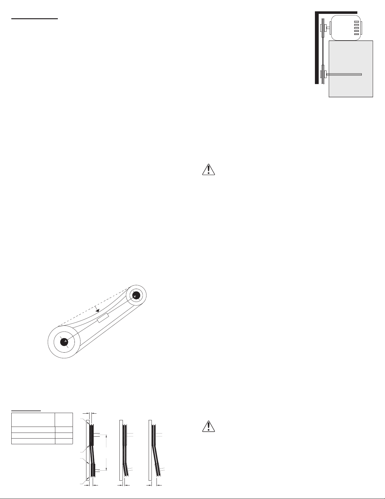
Figure 2 indicates where to measure
the allowable gap for the drive align-
ment tolerance. All contact points (in-
dicated by WXYZ) are to have a gap
less than the tolerance shown in the
table. When the pulleys are not the
same width, the allowable gap must
be adjusted by half of the dierence in
width. Figure 3 illustrates using a car-
penter’s square to adjust the position
of the motor pulley until the belt is par-
allel to the longer leg of the square.
Wiring Installation
Leave enough slack in the wiring to allow for motor move-
ment when adjusting belt tension. Some fractional motors
have to be removed in order to make the connection with the
terminal box at the end of the motor.
Refer to Wiring Diagrams, next page.
NOTICE! Follow the wiring diagram in the disconnect
switch and the wiring diagram provided with the mo-
tor. Correctly label the circuit on the main power box
and always identify a closed switch to promote safety
(i.e., red tape over a closed switch).
Fan Installation
The fan support (roof curb) should provide a level surface
for installation. If the roof is pitched more than 1/2:12, a sloped
curb must be used to correct for the incline. Place fan over
roof opening. Secure the fan with lag screws, anchor bolts or
other suitable fasteners.
For easier installation, larger size fans may be disassembled
on the ground and transported to the roof in sections. Howev-
er, if the sections are not assembled properly, the wheel may
rub against the fan inlet causing noise.
This can be prevented by:
• Ensuring the wheel is tightly fastened on the shaft.
• Ensuring the wheel is not dropped on the shaft before the
setscrews are tightened. Should interference occur, discon-
nect the power source. Refer to Bearing Replacement, page
5.
Final Installation Steps
1. Inspect fasteners and setscrews, particularly fan mount-
ing and bearing fasteners, and tighten according to the
recommended torque shown in the table, Recommended
Torque for Setscrews/Bolts, page 3.
2. Inspect for correct amperage and voltage with an amme-
ter and voltmeter.
3. Ensure all accessories are installed.
4. Inspect wheel-to-inlet clearance on power roof fans.
5. Test the fan to be sure the rotation is the same as indicat-
ed by the arrow marked Rotation.
NOTICE! Do not allow the fan to run in the wrong di-
rection. This will overheat the motor and cause seri-
ous damage. For 3-phase motors, if the fan is running
in the wrong direction, check the control switch. It is
possible to interchange two leads at this location so
that the fan is operating in the correct direction.
Installation
To prevent damage to the fan during shipping, motors 5 HP and
larger and extremely heavy motors (cast iron or severe duty) are
shipped loose and must be eld mounted by bolting the motor on the
motor mounting plate in the existing mounting slots.
Dampers
If your fan is supplied with dampers, follow the directions
below. If your fan does not include dampers, proceed to Belt
and Pulley Installation.
1. Place the damper inside the curb. Ensure the damper will
open freely for the correct direction of airow.
2. Secure to curb at the damper shelf.
3. Drill a hole in the curb shelf for conduit (needed for mo-
tor wiring).
4. Operate the dampers manually to ensure the blades move
freely. Dampers should be released from full open posi-
tion to check for proper closing.
5. Install fan over curb with the conduit location in line with
the conduit hole in the curb.
Belt and Pulley Installation
Belt tension is determined by the sound of the belts when
the fan is rst started. The belts will produce a loud squeal
which dissipates after the fan is operating at full capacity. If
belt tension is too tight or too loose, lost eciency and dam-
age can occur.
Do not change the pulley pitch diameter to change tension.
The change will result in a dierent fan speed.
1. Loosen the motor plate adjustment bolts on motor base
and move motor plate in order that the belts can easily slip
into the grooves on the pulleys. Never pry, roll, or force the
belts over the rim of the pulley.
2. Adjust the motor plate until proper tension is reached. For
proper tension, a deection of approximately 1/4” per foot
of center distance should be obtained by rmly pressing
the belt. Refer to Figure 1.
1 foot
1/4 inch
Figure 1
3. Lock the motor plate adjustment bolts in place.
4. Ensure pulleys are properly aligned. Refer to Figure 2.
Pulley Alignment
Pulley alignment is adjusted by loosening the motor pulley
setscrew and by moving the motor pulley on the motor shaft.
Figure 2
OFFSET ANGULAR OFFSET/ANGULAR
A
X
Y
Z
CENTER
DISTANCE
(CD)
Tolerance
Center Distance Max.
Gap
Up through 12” 1/16”
12” up through 48” 1/8”
Over 48” 1/4”
Figure 3


