Kool Karz Playground KKUTV-014 Manuel utilisateur

BATTERY POWERED RIDE-ON
Owner’s Manual
with Assembly Instructions
Styles and colo(u)rs may vary.
Made in China.
The owner’s manual contains important safety information as well as assembly, use and
maintenance instructions.
The Ride-on Car must be assembled by an adult who has read and understands the
instructions in this manual.
Keep the package away from children and dispose of properly before use.
Keep this manual for future reference.
UTV
Type without roof
KKUTV-014

Battery
Charger
12V10AH*1
12V1000mA
Suitable age:
Load Capacity:
Speed:
Size of car:
Power way:
Charge time:
37-96 months
Under 30kg
3-6 km/h
without roof 118 * 76 * 73.5 cm
Charging type
8-12 hours
About Your New Ride-On │ 1
VER: SMS-JS370-EN-20200721
SPECIFICATIONS:
On the purchase of your new Ride-On.
This ride-on will provide your child with many miles of riding of enjoyment. To
help assure you and your rider a safe ride we ask you to please read this manual
carefully, and keep it for future reference.
Follow the recommendations in this manual, they are designed to improve the
safety and operation of your ride-on car and it’s rider.

The following safety hazards may result in serious injury or death:
• Never leave child unattended. Direct adult supervision is required. Always keep child in view
when child is in vehicle.
• To reduce the risk of injury, adult supervision is required. Never use in roadways, near motor
vehicles, on or near steep inclines or steps, swimming pools or other bodies of water, always
wear shoes, and never allow more than 1 rider.
• Never use in unsafe conditions such as snow, rain, loose dirt, mud, sand, or gravel,
otherwise may result in an unexpected accident such as tipping over, and could damage the
electrical system or battery
• Not to be used in traffic.
• This toy should be used with caution since skill is required to avoid falls or collisions causing
injury to the user or third parties.
• This toy is unsuitable for children under 36 months due to its maximum speed; Maximum
user weight is 30kg.
• This toy has no brake.
User Notice │ 2
WARNING!
SAFETY
●Non-rechargeable batteries are not to be recharged.
●Rechargeable batteries are to be removed from the toy before being charged.
●Rechargeable batteries are only to be charged under adult supervision.
●Different types of batteries or new and used batteries are not to be mixed.
●Batteries are to be inserted with the correct polarity.
●Exhausted batteries are to be removed from the toy.
●The supply terminals are not to be short-circuited.
BATTERY INFORMATION
•CHOKING HAZARD - Small parts. Not suitable for children under 36 months. The product
contains small parts, keep children away when assembling.
•ADULT ASSEMBLY REQUIRED.
• Always remove protective material and poly bags and dispose before
assembly.
• Protective equipment should be worn. Always wear shoes and sit in the seat when operating
the vehicle.
• Only drive on level ground. Never use on the lawn.
• Never leave a child unattended.
• Keep your hands, hair, and clothes away from moving parts.

23
31
22
1
3
21
26
27
16
5
5
6
6
7
724
8
911 13
14
10
8
4
4
4
6
12
4
13
15
13
30
11
28
29
25
29
13
24
13
13
20
17
18
19
13
HINT: Some parts shown are assembled on both sides of vehicle
Parts Diagram │ 3
Type R/C
Basic type
=]]]

PART
NO.
REMARKS
PART NAME
Q’ty (pcs)
Vehicle body
Rear wheel
Front wheel
Ø12 washer
Lock nut
Split pin
Hubcap
Steering column
Steering wheel
M5x35 machine screw
Ø5 nut
Front bumper
Ø4x12 flat head screw
Bakset base
Bakset fence
Shift lever assembly
Protecting board
Seat
Seat back
M5x16 machine screw
Rear axle
Spanner
Charger
Ø4x12 round head screw
M5x25 machine screw
Taillight cover
Rear bed board
Rear rollbar linkage
Rear rollbar support
Front rollbar
Remote controller For R/C type only
Left and right
Left and right
Left and right
Parts List │ 4
without roof
1
2
3
4
5
6
7
8
9
10
11
12
13
14
15
16
17
18
19
20
21
22
23
24
25
26
27
28
29
30
31
1
2
2
8
4
5
4
1
1
1
5
2
22
1
1
1
1
1
1
2
1
2
1
4
4
2
1
1
2
1
1
1
2
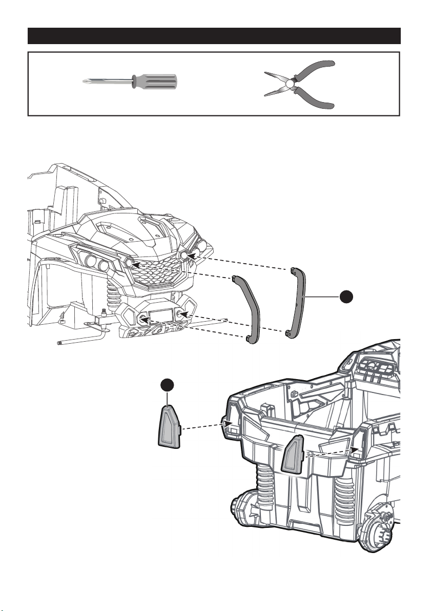
Attach the Front Bumpers & Tailight Cover │ 5
Assembly tools required (not included):
Screwdriver
Long nose pliers
1. Insert the tabs on the front bumper into the
holes on the front of the vehicle, push until
you hear it “click” into place.
2. Insert the left and right taillight covers
and “snap” into place.

2
3
1
Basic type - Attach the Steering Column │ 6
Turn the vehicle body downside up.
1. Slide a Ø12 washer onto the steering column from the straight end.
2. Insert the straight end of the steering column through the hole on bottom of the
vehicle body, and out through hole on the dash.
3. Slide a Ø12 washer onto the steering column from the bent end.
HINT: The follow steps only for the basic type.
Front Bottom View

1
2
Turn the vehicle body downside up.
1. Insert the straight end of the steering column through the hole on the steering gear
box, the hole on the vehicle body, and out through hole on the dash. Ensure the gear
part on the steering column matchs up with the steering gear box.
2. Slide a Ø12 washer onto the steering column from the bent end.
Type /RC - Attach the Steering Column │ 7
HINT: The follow steps only for the R/C type.
Front Bottom View

1
1
2
3
4
8-1
8-2
8-3
Reset the Front axle │ 8
Ø6 lock nut
Ø6 lock nut
Ø6 washer
Ø12 washer
Steering column
M6X20 machine
screw
Front axle
linkage
Split pin
Front axle plate
Front axle plate
Front Bottom View
Cut off the plastic tie on the front axle with scissors.
1,2. Adjust the front axle plate so that the axle is in the correct position as shown
(8-1);
3. Slide a Ø12 washer onto the steering column from the bent end.
4. Insert the split pin into the hole on the bent end of the steering column. Bend the
ends of split pin back using a long nose pliers (not included).
5. Remove the M6x20 machine screw, Ø6 washer and Ø6 lock nut from the front axle
linkage. Reinsert the M6x20 machine screw through the hole on the front axle
linkage, the Ø6 washer and the hole on the front axle plate, then fasten the Ø6 lock
nut to the opposite end of the screw with a Long Nose Pliers(Not included).
Tools required (not included):
Long nose pliers

1
2
3
4
6
5
Attach the Rear Wheels │ 9
Rear Bottom View
2. Slide the rear wheel onto the rear axle .
3. Slide the Ø12 washer onto the rear axle.
4. Tighten a lock nut to the end of the rear axle with a spanner.
Repeat the 2-4 steps for the other rear wheel.
HINT: An extra spanner has been provided to hold the Lock Nut on the other side of the rear
axle while tightening the Lock Nut on the other side. DO NOT over tighten.
5. Insert a split pin into the hole on the each end of the rear axle. Bend the ends of split pins
back using a long nose pliers (not included).
6. “Snap” a hubcap to each rear wheel.
Cut off the plastic ties on the gear boxes. Remove all the parts
from the rear axle.
1. Insert the rear axle through the hole in the vehicl body, when inserting it half way,
lift the another gear box so that the rear axle can go through it and protrude out.
Make sure that the rear axle is centered with left and right ends exposed the same
distance outside of the ride-on toy body.
Hole on the gear box
Table des matières
Autres manuels Kool Karz Playground Jouet


