KLR 950 Manuel utilisateur
1977
DEPUIS/SINCE
KLR 950
944, Des Hérons
Saint-Pie, (Qc) Canada
J0H 1W0
T: (450) 388-0404
T: 1-800-918-8777
www.klrsystems.com

0
Contents
SAFETY PRECAUTIONS ................................................................................................................................... 2
IDENTIFICATION ............................................................................................................................................ 4
The product brand and type designation ................................................................................................. 4
Version of product .................................................................................................................................... 4
Manufacturer contact: .............................................................................................................................. 4
PRODUCT SPECIFICATION ............................................................................................................................. 5
Range of applications intended use and general functions ...................................................................... 5
Dimensions (for transport) ....................................................................................................................... 5
Specification for electricity and air ........................................................................................................... 5
INSTALLATION ............................................................................................................................................... 6
Minimal space required ............................................................................................................................ 8
Location of the instructions .................................................................................................................... 10
OPERATION ................................................................................................................................................. 11
Main screen ......................................................................................................................................... 11
Load clips ............................................................................................................................................. 11
Ink jet printer setup ............................................................................................................................ 13
Turn ON the machine .......................................................................................................................... 15
Adjustment.......................................................................................................................................... 16
Go to advanced parameters ............................................................................................................... 16
Advanced parameters ......................................................................................................................... 16
Configurations ..................................................................................................................................... 19
Miscellaneous configuration ............................................................................................................... 22
Hardware configuration .......................................................................................................................... 22
MAINTENANCE AND CLEANING .................................................................................................................. 23
Preventive maintenance schedule .......................................................................................................... 23
Maintenance steps ...................................................................................................................................... 24
Changing belts ..................................................................................................................................... 24
Driving belt motors ............................................................................................................................. 33
Disassemble half of top belt holder .................................................................................................... 34
Feeder motors ..................................................................................................................................... 35
Replacing the jewelry saw................................................................................................................... 36

1
Replacing the feeding sensor .............................................................................................................. 38
Replacing the finger sensor ................................................................................................................. 39
24 volts power supply ......................................................................................................................... 39
MAINTENANCE AND REPARATIONS BY TECHNICIANS FROM KLR SYSTEMS INC. ....................................... 40
Contact information for service technicians ............................................................................................... 40
LISTS OF SPARE PARTS AND CONSUMABLES .............................................................................................. 41
CHECK LIST .................................................................................................................................................. 42
DECOMMISSIONING OF THE PRODUCT ...................................................................................................... 43
INDEX .......................................................................................................................................................... 43
2
SAFETY PRECAUTIONS
CAUTION
The equipment described in this manual is covered with fix panel (only opened with a tool) that
provide protection from electrical components and most of mechanical motions. However,
there is four (4) belts that can be exposed to the user. ALWAYS turn OFF the machine before
approaching hands from every motion part to remove a jam, service or clean the machine. Go
against this notice can result in a severe injury or death;
The equipment described in this manual is designed and manufactured to the highest KLR
standards. Special attention made to ensure that the operation of the machine is safe and
convenient without compromising the efficiency. Keeps hands away from the working area of
the machine.
Keep hands away from the working machine. Do not force through gaps or from the top;
If the system is linked to another machine or install onto another machine. Lock the electrical
box of the other machines before performing any maintenance on this equipment. Please refer
to the local regulations and laws on locking out machinery. Go against this notice can result in
a severe injury or death;
When working on the electrical components. Disconnect the equipment at the source and use
a lockout device to avoid any risk of danger. Make sure you also have the space required to
complete the work to avoid any risk of danger.
Any modifications with any aspect of the mechanical, safety, electrical design, design, or any
parts connected with the equipment will void the warranty and liability of KLR Systems. If a
change is required, contact KLR Systems for approval. All technical handling must be done by a
qualified technician or by KLR Systems;
KLR is not responsible for any abuse, mishandling, misuse, improper maintenance and repair
by owners and users;
Equipment must be supervised when operating;
Continue the next page…
3
CAUTION
Safety switches: DO NOT bypass any safety components for any reason. Violation will void all
warranties and responsibility from KLR Systems. If a safety component is broken, it must be
replaced before starting the machine;
Safety panel (fix panel) or safety doors: As a safety, component does not try to remove or
unscrew them unless it is necessary for a maintenance operation. If it is the only option, use a
lockout device during this procedure and reassemble every single piece as it was when finished.
4
IDENTIFICATION
The product brand and type designation
KLR.950
Bag closer
*The machine in the picture is a left version
Version of product
Serial number: located on the opposite side of the touch screen.
Manufacturer contact:
KLR SYSTEMS INC. Packaging equipment manufacturer
Address: 944 Herons street,
City, province, country: Saint-Pie, Quebec, Canada
Zip code: J0H 1L0
Phone number: 450-388-0404
Web site: http://klrsystems.com/

5
PRODUCT SPECIFICATION
Range of applications intended use and general functions
The bag closer KLR.950 is designed to close bag tail with plastic clip. The machine tells the user
whenever clip is running out. These following values are in the prototype version and are subject to
change:
Speed in between 50 and 60 package a minute;
Uses a convenient touch screen (HMI);
Uses a recipe and ingredient method, can be finetuned according to the product easily;
A KLR 930 Air printer or an ink jet printer can be installed on the equipment;
Made of stainless steel 304 and anodize aluminum;
Equipped with an Ethernet communication device;
Easy clip loading and does print automatically when loading (if set in the parameters);
Ambidextrous machine (left or right).
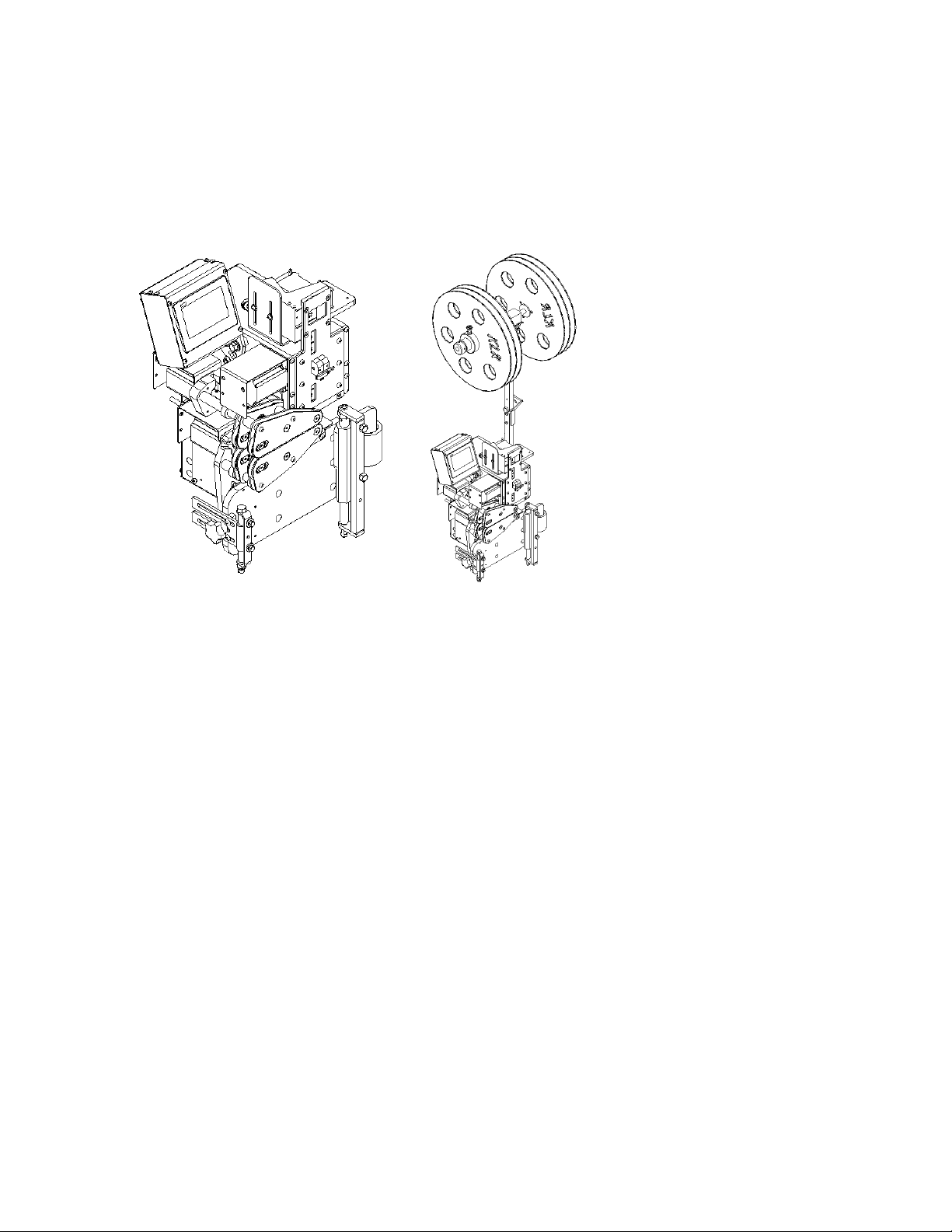
Dimensions (for transport)
The clips holder can be disassembled from the body of the machine in order to save space.
Height: 24 inches
Length: 16 inches
Width: 15 inches
Specification for electricity and air
This machine is intended to use these specifications:
Electrical need: 120 Volts – 5 Amps – 1 Phase – 60 Hertz (access within 5 feet from the machine)
Need a 3 pins female jack power cord adapter 18AWG. Provided in the packaging with the machine:
PE-01531-15-5P-6
In case of loss, order from KLR to get a new one and be sure to have the cord as per requirement for
your machine.
Pneumatic need: None. Air printer is sold separately (see air printer manual if needed)
6
INSTALLATION
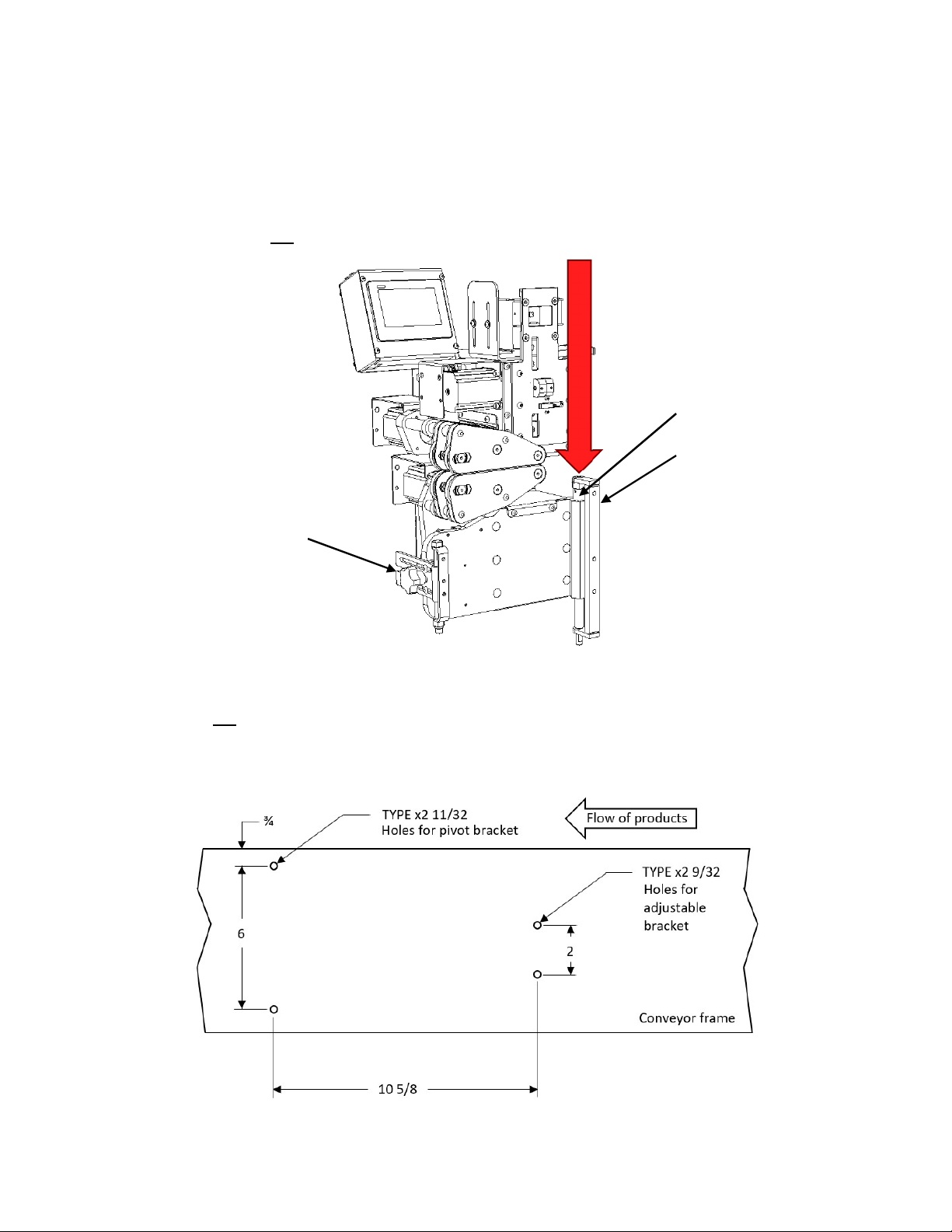
Mounted directly on a conveyor:
Of course, the KLR.950 is designed to be installed on KLR equipments, such a conveyor. The brackets are
attached to the body and are easy for removing quickly the machine from the conveyor. Take note this
following machine is a left version:
In case the machine is needed to be installed on a different conveyor: Take note this following bolt
patern is for a left version. Hardware needed for the pivot bracket are 5/16-24 screws. Hardware
needed for the adjustable bracket are 1/4-28 screws. It is recommended to use flat headed screws in a
thick wall conveyor since it is required to be screwed from inside the conveyor:
Pivot
bracket (hold weight)
Adjustable bracket (adjust the angle)
Adjustable
rod (height)
Pu
sh the
plunger to release
*Dimensions are in inches
7
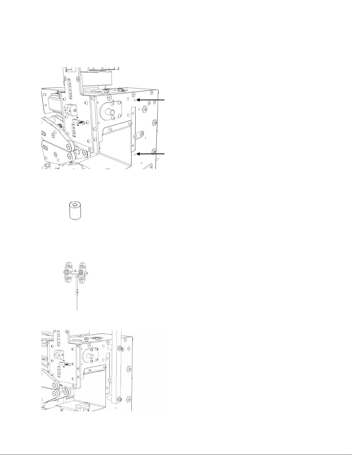
Assembling the clips holder:
The clips holder is attached with these threaded 1/4-20 holes:
To install it, it is needed:
Two (2) PM-00278;
Two (2) 1/4-20 socket head 2 ¼ inches long;
Two (2) 1/4 washer;
Two (2) 1/4 lock washer;
Clips holder.
Final result:
8
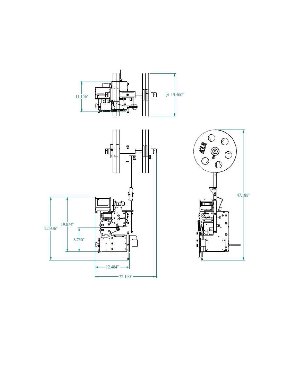
Minimal space required
Minimal space required to install this equipment. Here are the overall dimensions of the KLR.950 alone:
Autres manuels pour 950
1
Table des matières
Autres manuels KLR Équipement industriel


