Kioto Solar FWS 20 E Guide rapide

InstallatIon and InstructIon manual FRESH watER Station
1
E & OE, subject to change without notice.
Installation and Instruction manual
FRESH WATER STATION EN
October 2015
FWS 20 E FWS 30 E
FWS 35 E FWS WP E
Tank- and Wall fastening

2
E & OE, subject to change without notice.
Table of contents
Usage 3
Terms of warranty 3
Safety instructions and symbol legend 3
Safety instructions 3
Symbol legend 4
Scope of delivery 4
Provisions 5
Statutory provisions 5
Manufacturer’sspecications 5
Technical data 6
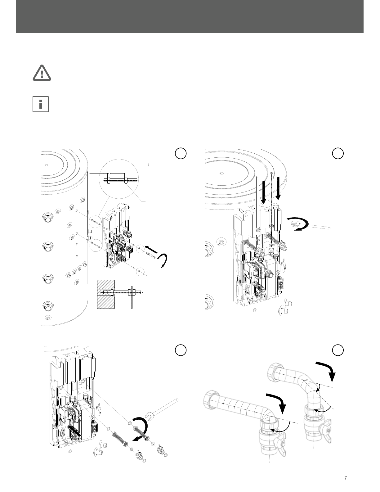
Installation 7
Installation on buffer tank 7
Wall fastening 8
Hydraulic installation 9
Circulation unit (optional) 9
Design of circulation unit 9
Installation of circulation unit 10
Electrical connection of circulation unit 10
Operating modes of circulation unit 11
Initiation 12
Malfunctions 12
Constant circulation mode 12
Fresh Water Station leaks 12
No hot water 13
Kein Zirkulationsbetrieb 13
No/wrong switching times 13
Drilling plan for wall fastening 14
Overview connections FWS+HKG+SST fresh water tank 15
Cascade circuit 16
Notes 17
Inhaltsverzeichnis

InstallatIon and InstructIon manual FRESH watER Station
3
E & OE, subject to change without notice.
Usage
The Fresh Water Station is used to heat up tap water in connection with a buffer tank.
It will be installed next to the buffer tank at the wall or directly onto the buffer tank at special system solutions.
Another use or installation is not intended.
The manufacturer is not liable for damages due to inappropriate use and the operator bears the risk.
Do not connect the Fresh Water station directly to any heat generator.
TheFreshWaterStationincludesaself-sufcientregulationandcanbeupgradedwithanoptionalcirculationunit
Safety instructions and symbol legend
Safety instructions
• Theinstallation,initiationandmaintenancemustonlybeaccomplishedbyqualiedtechnicalprofessionals.
The operation of this device is not allowed to persons (including children) with limited physical, sensory or intellectual
abilities. Uninformed or unacquainted persons may operate the device only under the supervision or at a trained
person’s disposition.
• Replacements or repairing of electrical parts like the power cord must be conducted by a professional electrician.
• Follow the instructions in this manual closely to ensure proper functioning.
• Exclusively use the Fresh Water Station for heating up tap water.
• Only install the device in dry and frost-free locations.
• Operate the device only at ambient temperatures between +2°C and +40° C.
• Interrupt the power supply of the heating system (230 V/AC) prior to installation.
• During operation the device can heat up and burns are possible.
• The device must be connected to an external circuit breaker to allow a shutdown at any time.
• Installation and operation must be performed according to regional laws, regulations and common practice
• At the occurrence of malfunctions – regardless of nature – please contact your authorized technical professional.
Terms of warranty
The Manufacturer issues a warranty of two years from the invoice date on the device and its constituent parts.
Without proper installation and use of the device the warranty is void.

4
E & OE, subject to change without notice.
Symbol legend
Safety instructions
are marked with a warning triangle as illustrated on the left.
Safety instructions indicate important information for potentially dangerous situations for person and device. Additional
buzzwords describe nature and severity of the danger.
Advices
are marked with an information sign as illustrated on the left.
Advices highlight important information for situations without severe danger for person and device.
Screw wrench
indicates the maximum tightening torque and the rotational direction. max. tightening tourque [Nm]
Scope of delivery
Fresh Water Station
Connection Set
Mounting Set

InstallatIon and InstructIon manual FRESH watER Station
5
E & OE, subject to change without notice.
Mounting Set
Statutory provisions
TheDevicemustbeinstalledandoperatedaccordingtothefollowingnormsandcountryspecicdirectivesandprovisions:
DIN EN 12828
DIN 1988
DIN 4708
DIN 4753
DIN 4757
DIN 18380
DIN 18381
DIN 18382
DIN EN 12975
VDE 0100
VDE 0185
VDE 0190
ÖNORM H5195
Material damage
Deviations from the values stated in table 1 may lead to damages and functional limitations of the device.
Noncompliance with these values leads inevitably to a loss of guarantee.
ForoperatingtheFreshWaterStation,thefollowingspecicvalueshavetobeadhered:
Dissolved matter Unit Speci c values (copper brazed)
pH-value 7-9 (considering Saturation index)
Saturation index (delta pH-value) -0,2 < 0 < +0,2
Degree of hardness °dH 6-15
Conductivity μS/cm 10...500
Filterable matter mg/l <30
Free chlorine mg/l <0,5
Hydrosulde(H2S) mg/l <0,05
Ammoniac (NH3/NH4+) mg/l <2
Sulfate mg/l <100
Hydrocarbonate mg/l <300
Hydrocarbonate/Sulfate mg/l >1,0
Sulde mg/l <1
Nitrate mg/l <100
Nitrite mg/l <0,1
Iron, solute mg/l <0,2
Manganese mg/l <0,1
Free aggressive carbonic acid mg/l <20

6
E & OE, subject to change without notice.
Technical data
1 Thermostatic head
2 Electricity box
3 Plate heat exchanger
4 Flow-Switch
5 HE Charge pump
6 Coiled probe
7 Push-in connection for circulation unit
(incl. blind cap)
8 Circulation unit (optional)
A Cold water
B Hot water
CFrombuffertank(ow)
D To buffer tank (return)
E Circulation pipe (not included)
D
A
C
B
4
5
63
2
8
7
1
E
Fresh water station FWS 20 E FWS 30 E FWS 35 E FWS WP E
Output [l/min] 20 30 35 30
Heat exchanger [plates] 21 29 41 49
Weight [kg] 15 17 19 21
Charge pump
Voltage [V (Hz)] 230 V (50 Hz)
Rotation speed [U/min] 800 - 4660
Power input [W] 3 - 45
Nominal current [A] 0,03 - 0,44
Circulation unit
Voltage [V (Hz)] 230 V (50 Hz)
Power input [W] 8
Nominal current [A] < 0,1
Max. operating pressure
Tap water circuit [bar] 10
Buffer water circuit [bar] 3
Insulation [material] EPP
Temperatures min. - max.
Ambiance [°C] 2 - 40°
Buffer water [°C] 2 - 95
Dimensions W x H x D [mm] 400 x 800 x 330
Connections
Cold water G1" IG
Hot water G1" IG
Bufferow G1" AG
Buffer return G1" AG
Circulation G½" IG

InstallatIon and InstructIon manual FRESH watER Station
7
E & OE, subject to change without notice.
90°
90°
45°
Installation
Material damage
Avoid tightening torque and force effects on already installed parts and connections of the device.
Regulation
TheFreshWaterStationincludesaself-sufcientregulation.Anadditionalexternalregulationisnotintendedandnotallowed.
Installation on buffer tank
1
2
3
4
Installation of Fresh Water Station Installation of water piping
Shaping of exible hosesInstallation of connection set
Schnitt A-A
M1 : 1
AA
ca. 10 ca. 40
max. 10 Nm
A
1
max. 70 Nm
2
max. 70 Nm
3

8
E & OE, subject to change without notice.
5
Final assembly of shaped connection set
Wall fastening (Drilling plan for wall fastening on page 14)
max. 70 Nm
5
Schnitt A-A
M1 : 3
AA
12
12
12
80min.
60 90
10
M
36
0
max. 70 Nm
20
A
1
2
A
1
2
3
4
max. 10 Nm

InstallatIon and InstructIon manual FRESH watER Station
9
E & OE, subject to change without notice.
Hydraulic installation
Install the hydraulic piping according to the instructions in chapters "Installation on buffer tank" and "Wall fastening".
Piping
Piping between buffer tank and Fresh Water Station ought to be as short as possible.
When using different piping materials take care of the installation sequence to avoid electrochemical corrosion
Personal and material damage
Thetapwatersupplyneedstobeconstructedaccordingtospecication(Picturebelow).
9
13
14 10
15 16 14 K
17
Specication of tap water supply
9 Expansion vessel (optional)
10 Manometer
13 Security valve (6 bar)
14 Cut-off valve
15 Backowpreventer
16 Pressure reducer (necessary if K >= 6 bar)
17 Finelter
K Tap water main connection
Circulation unit (optional)
This chapter is only relevant for Fresh Water Stations with a circulation unit.
Design of circulation unit
1 Circulation pump
2 Gasket ring
3 Plug-in adapter
4 Non-return valve
5 Flat gasket
6 Cut-off cock
7 Swivel nut
8 Eccentric tappet
9 Circulation pipe
(not included)
optional
1
3
8
9
7
6
2
5
5
4

10
E & OE, subject to change without notice.
Installation of circulation unit
Personal and material damage
Sufcientexpansionandoverpressuresafetydevicesmustbeinstalledinthecirculationcircuit
A rinsing port needs to be installed in the circulation circuit.
Electrical connection of circulation unit
Danger to life
Manipulation of electrical parts must be conducted by a professional electrician.
Deenergize the device before opening it. Local regulations must be observed!
Connect the circulation unit according to the desired operating mode.
Detail A
M1 : 2
Detail B
M1 : 2
A
B
1
2
3
4
5
Ce manuel convient aux modèles suivants
3
Table des matières
Manuels Chauffe-eau populaires d'autres marques

Kenmore
Kenmore 153.582400 Manuel utilisateur

Applimo
Applimo Edel AIR Manuel utilisateur

STIEBEL ELTRON
STIEBEL ELTRON Eltronom SHU 5 S Manuel utilisateur

clage
clage E-Mini Series Manuel utilisateur

Toyotomi
Toyotomi Oil Miser OM-180 Manuel utilisateur

Bradford White
Bradford White EF Series Manuel utilisateur