
Kewtech KT62 Manuel utilisateur
KEWTECH
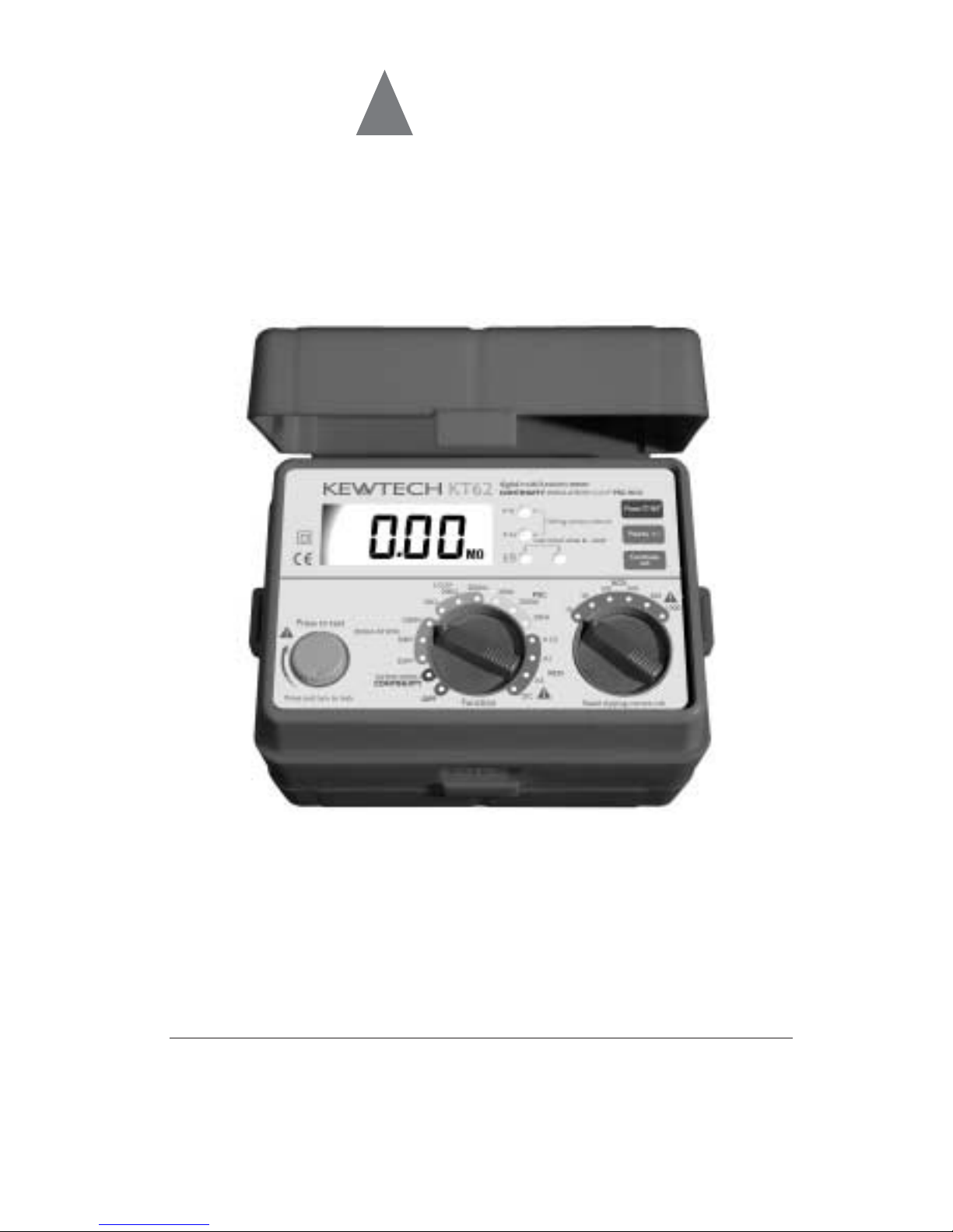
KT62 digital multi function tester
Instruction manual

Contents 1 Safe testing 1
2 Features 3
3 Specification 6
4 Continuity (resistance) tests 9
4.1 Instrument layout 9
4.2 Test procedure 9
5 Insulation tests 11
5.1 The nature of insulation resistance 11
5.1.2 Capacitive current 11
5.1.3 Conduction current 12
5.1.4 Surface leakage current 12
5.1.5 Total leakage current 13
5.2 Damage to voltage sensitive equipment 13
5.3 Preparation for measurement 14
5.4 Insulation resistance measurement 14
6 Loop Impedance tests 17
6.1 Voltage measurement 17
6.2 What is earth fault loop impedance? 17
6.3 Automatic over temperature cut out 17
6.4 The loop impedance test 17
6.5 Loop impedance at 3 phase equipment 19
7 Prospective Short Circuit Current (PSC) tests 21
7.1 What is Prospective Short Circuit? 21
7 2 Testing Prospective Short Circuit Current 21
8 RCD tests 23
8.1 Purpose of RCD Test 23
8.2 What does the RCD test really do 23
8.3 RCD testing 23
8.4 Testing RCD's used to provide supplementary protection 24
8.5 Testing time delayed RCD's 25
8.6 Testing DC sensitive RCD's 25
9 General 26
10 Battery replacement 26
11 Fuse replacement 26
12 Servicing 27
13 Case and strap assembly 27

1 Safe Testing
1
Electricity is dangerous and can cause injury and death. Always
treat it with the greatest of respect and care. If you are not quite
sure how to proceed, stop and take advice from a qualified person.
1 This instrument must only be used by a competent and trained person
and operated in strict accordance with the instructions. Kewtech will
not accept liability for any damage or injury caused by misuse or non-
compliance with the instructions or with the safety procedures.
2 It is essential to read and to understand the safety rules contained in
the instructions. They must always be observed when using the
instrument.
3 This instrument is intended only for single phase operation at 230V AC
+10%-15% phase to earth or phase to neutral operation, and then
only for loop, prospective short circuit current (PSC) and RCD testing.
For use in the continuity testing and insulation testing modes this
instrument must be used ONLY on circuits which are de-
energised.
4 When conducting tests do not touch any exposed metalwork
associated with the installation. Such metalwork may become live for
the duration of the test.
5 Never open the instrument case (except for fuse and battery
replacement and in this case disconnect all leads first) because
dangerous voltages are present. Only fully trained and competent
electrical engineers should open the case. If a fault develops, return the
instrument to Kewtech for inspection and repair.
6 If the overheat symbol appears in the display disconnect the
instrument from the mains supply and allow to cool down.
7 For loop impedance tests to prevent unwanted tripping during loop
testing all residual current devices (RCDs) must be taken out of the
circuit and temporarily replaced with a suitably rated MCB unit. The
RCD must be replaced after the loop test is completed.
8 If abnormal conditions of any sort are noted (such as a faulty display,
unexpected readings, broken case, cracked test leads, etc) do not use
the tester and return it to Kewtech for repair.
9 For safety reasons only use accessories (test leads, probes, fuses,
cases, etc) designed to be used with this instrument and
recommended by Kewtech. The use of other accessories is prohibited
as they are unlikely to have the correct safety features.
10 When testing, always be sure to keep your fingers behind the safety
barriers on the test leads.

Safe testing
2
11 During testing it is possible that there may be a momentary
degradation of the reading due to the presence of excessive transients
or discharges on the electrical system under test. Should this be
observed, the test must be repeated to obtain a correct reading. If in
doubt, contact Kewtech.
12 The sliding shutter on the back of the instrument is a safety device. The
instrument should not be used if it is damaged or impaired in any way,
but returned to Kewtech for attention.
13 Kewtech recommends the use of fused test leads particularly when
measuring voltages in high energy circuits. Where assessments show
that the risk is significant, then the use of fuse test leads constructed in
accordance with the HSE Guidance Note GS38 should be used. The
test accessories used with this instrument for loop impedance and
RCD tests are all fused.
14 Do not operate the function selector whilst the instrument is
connected to a circuit. If, for example, the instrument has just
completed a continuity test and an insulation test is to follow,
disconnect the test leads from the circuit before moving the selector
switch.
15 Do not rotate function dial when test button is depressed. If the
function switch is inadvertently moved to a new function when the test
button is depressed or in lock-down position the test in progress will
be halted.
16 Always check the test lead resistance before carrying out tests. This
ensures the leads are ok before taking measurements. The resistance
of leads and/or crocodile clips may be significant when measuring low
resistances. If crocodile clips can be avoided for low resistance
measurements , this will reduce the error due to lead accessories
17 When carrying out Insulation Resistance tests, always release the test
button and wait for charged capacitances to totally discharge before
removing the test leads from the test circuit.
BATTERY LIFE
Always switch the selector dial to the OFF position after each testing
period. This will conserve battery power.
INSULATION/CONTINUITY TESTS
Only use the test leads supplied with this tester and always ensure that
they are plugged fully into the unit’s 4mm terminals to guarantee a
sound and proper connection.

2 Features
3
Connector
Live circuit LED
Phase switch
Polarity switch
Continuity null switch
RCD rated tripping
current switch
Function switch
Wiring check LED
LCD display
Test button
LCD display
Test Lead with IEC Connector
Test Lead for Continuity
and Insulation Testing
Fig. 1

Features
4
The KT62 Multi-Function tester performs six functions in one instrument.
1 Continuity tester
2 Insulation resistance tester
3 Loop impedance tester
4 Prospective short circuit current tester
5 RCD tester
6 Mains voltage warning when operating the loop impedance and
RCD mode.
The tester is designed to Safety Standard IEC 1010-1/BS EN 61010-1
CAT III(300V).
The instrument is supplied with:
1Adistribution board or lighting circuit test lead for
LOOP/PSC/RCD testing.
2 A lead for LOOP/RCD testing at socket outlets.
3 A lead for insulation and continuity testing.
4 External Earth Probe for loop testing.
In the insulation resistance testing mode the instrument provides a rated
current of1mA as required in BS 7671 (IEE Wiring Regulations) and BS EN
61557-2 1997.
In the continuity testing mode the instrument provides a short circuit
current of 200mA as required in BS 7671 (IEE Wiring Regulations) and BS
EN 61557-4 1997.
Continuity and insulation resistance functions have the following features:
Live circuit warning A colour coded LED warns if the circuit
under test is live.
Continuity Null Allows automatic subtraction of test
lead resistance from continuity
measurements.
Polarity switch Allows switching of polarity during
continuity tests.
Auto discharge Electric charges stored in capacitive circuits
are discharged automatically after testing
by releasing the test button.

Features
5
Loop impedance, PSC and RCD testing functions have the following
features:
Voltage level In the LOOP/PSC/RCD modes, supply
voltage is displayed when the instrument is
connected to the supply until the test button
is pressed.
Wiring check Three LEDs indicate if the wiring of the
circuit under test is correct.
Over temperature Detects overheating of the internal
protection resistor (used for LOOP and PSC tests) and of
the current control MOS FET (used for RCD
tests) displaying a warning symbol and
automatically halting further measurements.
Phase angle selector The test can be selected from either the
positive (0˚) or from the negative (180˚) half-
cycle of voltage. This selector is used in the
RCD mode to obtain the maximum trip time
of an RCD for the test selected.
DC Test Allows testing of RCDs which are sensitive to
DC fault currents.
Auto data hold Holds the displayed reading for a time after
the test is complete.
Auto power off Automatically switches the instrument off
after a period of approximately 10 minutes.
The Auto power off made can only be
cancelled when the Function switch is
switched to the OFF position and then back
on.
V-NE Monitoring Automatically aborts measurement when the
Circuit N-E voltage rises to 50V or greater on RCD
ranges.

Specification
6
Measurement Specification
Function Open Circuit
Voltage (DC)
Short Circuit
Current Range Accuracy
Function Open Circuit
Voltage (DC)
Rated
Current Range Accuracy
Function Rated
Voltage (AC)
Nominal Test
Current at 0Ω
External Loop
Range Accuracy
Continuity Greater than
6V
Greater than
200mA as per
BS7671
20/200/2000Ω
Auto-Ranging
±(1.5%rdg
+3dgt)
250V+40%
-0%
1mA or greater
@ 250kΩas per
BS7671
20/200MΩ
Auto-Ranging
±(1.5%rdg
+3dgt)
500V+30%
-0%
1mA or greater
@ 500kΩas per
BS7671
20/200MΩ
Auto-Ranging
±(1.5%rdg
+3dgt)
1000V+20%
-0%
1mA or greater
@ 1MΩas per
BS7671
20/200MΩ
Auto-Ranging
±(1.5%rdg
+3dgt)
Insulation
Resistance
230V+10% -15% 50Hz
230V+10% -15% 50Hz
230V+10% -15% 50Hz
Loop
Impedance
25A
15mA
15mA
±(3%rdg+4dgt)
±(3%rdg+8dgt)
±(3%rdg+4dgt)
20Ω
200Ω
2000Ω
230V+10%
-15% 50Hz
Prospective
Short Circuit
Current
(PSC)
15mA
25A
25A
PSC accuracy is
derived from
measured loop
impedance
specification
and measured
voltage
specification
200A
2000A
20kA

Specification
7
Function Rated
Voltage (AC)
Trip Current
Trip Current
Duration
Accuracy
Function Rated voltage Measuring
Range Accuracy
Voltage measurement- 100-250V 100-250V 3% rdg
RCD
x 1/2
230V+10%
-15% 50Hz
230V+10%
-15% 50Hz
Trip Current:
-10% +0% of
range at 230V
Trip Current:
+10% -0% of
range at 230V
Trip Current:
+10% -0% of
range at 230V
RCD
x 1
10/30/100/300/
500/1000 mA
10/30/100/300/
500/1000 mA
2000ms
2000ms
1000mA
@200ms
Trip Current:
±10% of
range at 230V
RCD
x 5
230V+10%
- 15% 50Hz
10 mA
30/100/300mA
(Note: on x5 range
max. current that can
be generated is 1A)
50ms
Trip
Time±
(1% rdg
+3dgt)
To prevent wrong connection of test leads and to maintain safety, the
dedicated terminals used for continuity and insulation tests are
automatically covered when using the terminals for loop impedance, PSC
and RCD tests.
Instrument dimensions130 X 183 X 100mm
Instrument weight 1130g including batteries.
Reference conditions Specifications are based on the following
conditions except where otherwise stated:-
1Ambient temperature: 23±2˚C
2Relative humidity 45% to 75%
3Position: horizontal
4AC power source 230V, 50Hz
5DC power source: 12.0 V, ripple content
1% or less
6Altitude up to 2000m

Specification
8
Battery type Eight AA ALKALINE batteries.
Low battery warning symbol appears in the display and the
buzzer beeps if the battery voltage drops
below 7.8V.
Operating temperature 0 to +40˚C, relative humidity 80% or less, no
and humidity. condensation.
Storage temperature -10 to +50˚C, relative humidity 75% or less,
and humidity no condensation.
LED indication of live Illuminates if there is an alternating voltage of
circuit warning 50V AC or more in the circuit under test
before continuity or insulation resistance tests.
When DC voltage is detected across the
measuring terminal the LED lights up.
LED indication of The P-E and P-N LEDs illuminate when the
correct polarity wiring of the circuit under test is correct.
The reverse lamp is lit when P and N are
reversed.
Auto data hold In the loop impedance, PSC and RCD test
functions, the LCD reading is automatically
frozen for 3 seconds after measurement.
Display The liquid crystal display has 3 1/2 digits with a
decimal point and units of measurement (Ω,
MΩ, A, kA,V and ms) relative to selected
function. The display is updated approximately
five times per second.
Overload protection The continuity test circuit is protected by a
0.5A 600V fast acting (HRC) ceramic fuse
mounted in the battery compartment, where a
spare fuse is also stored.
The insulation resistance test circuit is
protected by a resistor against 1000 V AC for
10 seconds.
Mains Voltage On connecting test leads to the circuit under
Indication test on LOOP, PSC and RCD ranges, the LCD
reads V-PE. Sign ‘V-PE Lo’ or ‘V-PE Hi’ is also
shown when the voltage is 100V or less, or
260V or greater respectively.
+_
LO
Table des matières
Autres manuels Kewtech Multimètre


Manuels Multimètre populaires d'autres marques


Gossen MetraWatt
Gossen MetraWatt METRAmax 6 Manuel utilisateur

PeakTech
PeakTech 4000 Manuel d'utilisation et d'entretien

YOKOGAWA
YOKOGAWA 90050B Manuel utilisateur

Gossen MetraWatt
Gossen MetraWatt METRALINE DMM16 Manuel utilisateur

Fluke
Fluke 8846A Manuel d'utilisation et d'entretien

Tempo Communications
Tempo Communications MM200 Manuel utilisateur


