
KEEWAY ATV250 Guide d'installation et d'utilisation

1
ATV Service and
Maintenance Manual
Model: ATV250
C o p y r i g h t :
K E E WAY I N T E R N AT I O N A L D E V E L O P M E N T C O . , LT D .
FEB.2006

2
If you have any problems can not fnd the solution in this manual,
please fell free to contact with:
KEEWAY INTERNATIONAL DEVELOPMENT CO.,LTD
2000 SZENTENDRE U.8 KOZUZO. HUNGARY
TEL:0036-26-500005
FAX:0036-26-312034
EMAI: info@keewaymotor.com
Our engineer are very glad to give you the necessary assistance and help.

3
C O N T E N T
A. General information
1. Basic terminology- Engine
2. Engine types-4 stroke engine work cycle/illustrations
3. Workshop safety
Service rules
Electricals safety
B Product
1. Technical specifications
2. Special service tools
3. Engine and transmission
a) Specified torque value
b) Small but vital component /Nondirectional fitment-parts of engine
c) Engine removal /installation
d) Engine assembly
e) Radiator assembly
f) Engine removal /installation
Intake pipe of carburetor /Gear case/Cylinder head /Piston/Left crankcase cover / Water
pump/Right crankcase cover/Spare parts for right crankcase cover/ Clutch/Drive gear
COMP/Driven wheel clutch COMP/Crankcase/Speed gear box
g) Power flow chart
h) Lubrication system
i) The setup of valve interval
j) Engine cylinder compression test
k) Some important dimensions-engine
Fuel –air system - Air filter/Carburetor assy
- Mixed air ( air burning) system
- Disassembly and assembly of the carburetor
4. Chassis group
a) Specified torque value – chassis
b) Sub assembly – chassis
(i) Front wheel assy
(ii) Front disc brake assy
(iii) Redirector, upper and lower swing arm assy
(iv) Steering system
(v) Rear wheel, transmission system assy
(vi) Rear hydraulic brake assy
(vii) Rear swing arm assy
c) Important tips on vehicle assembly
d) Important dimensions of vehicle
5. Electricial /electronics

4
a) Magneto(A.C.G)
b) Wiring diagram
c) Ignition circuit test
d) The relational matters of the battery
e) The process of debugging of battery
f) Signal system circuit
g) Battery charging system circuit
h) Power flowing chart of electric start
i) Removal and replacement of various bulbs
j) Testing procedure of electrical components
k) Important specifications -electrical
C Others
1. Pre-delivery inspection (P.D.I)/check points
2. Periodical maintenance
3. Do’s and don’t’s
4. Safety ride
(i) Riding posture
(ii) Effective braking
5. Trouble shooting

5
A
GENERAL INFORMATION

2
B a s i c t e r m i n o l o g y - E ng i n e
A.
..
.Dead center
Either of the two limits in the cylinder at which the
piston changes its moving direction.
TDC ------- top dead center(the upper limit of the piston
movement)
BDC------- bottom dead center(the lower limit of the
piston movement)
B. Bore
Bore is the internal diameter of the cylinder block
C. Stroke
The length of the piston travel is called the stroke.
When piston moves from TDC to BDC, it is one stroke.
D.
D. D.
D. Displacement
The volume swept by piston when traveling from TDC to BDC is
called displacement. Normally displacement is measured in
CC( cubic centi-meter) e.g. 75cc, 125cc etc. and it varies
according to engine type.
E. Torque
Torque is a kind of twisting or turning force. When we loosen
or tighten the screws or bolts, we impart the torque to them.
The engine imparts torque to the wheels to drive them, and
imparts more torque when it climbs. The produce of strength and
the arm of force equal to the torque, and its unit is kilogram-meter.
F. The timing of ignition.
The ignition is timed in order to control the combustion
in the firebox. The timing ignition of ATV250 engine
changes as follows: 150。When it is 5000RPM.
3
Engine work cycle
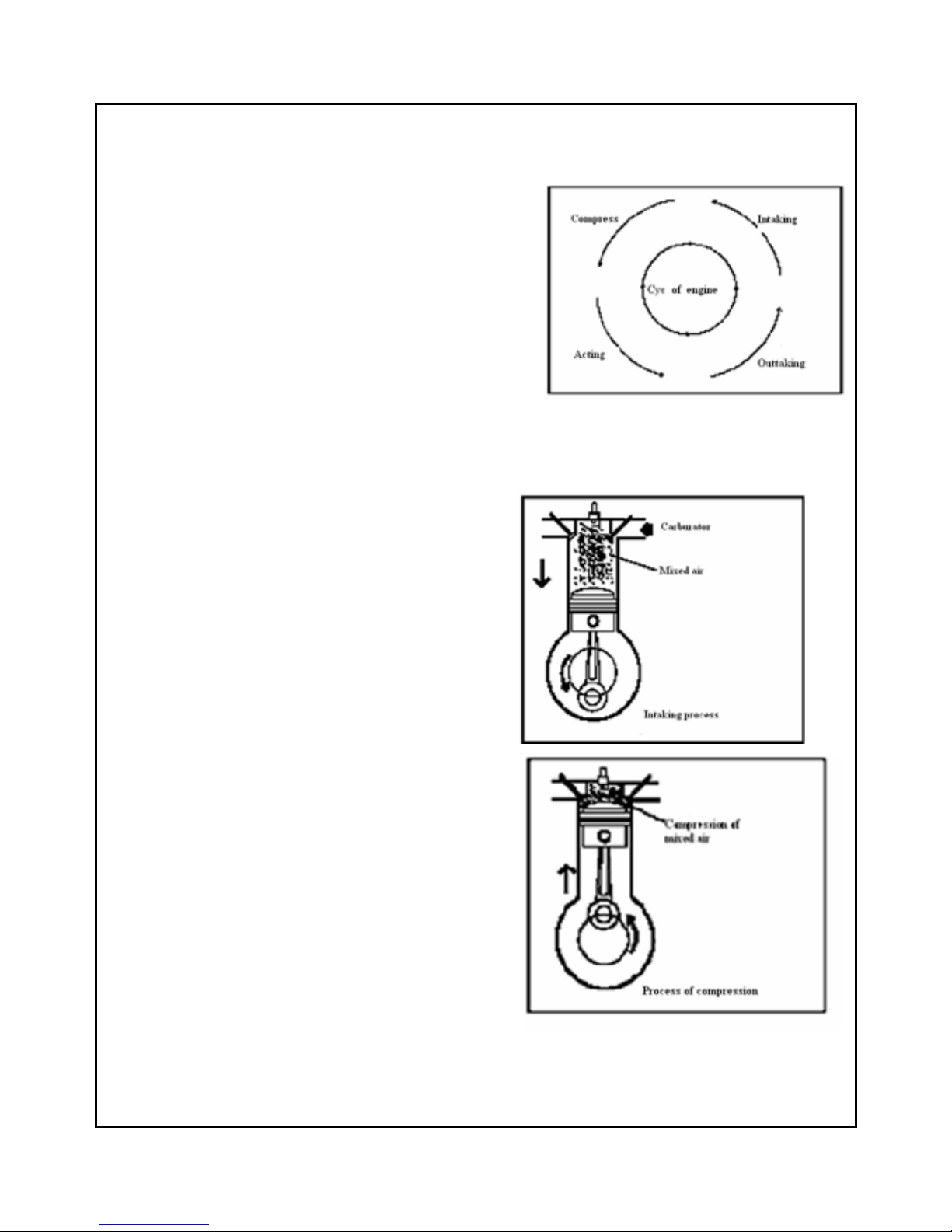
Each 4-stroke petrol engine has the following 4 processes the completion of these 4 processes is termed as one cycle
of the engine work.
1、Suction: air and fuel mixture is sucked inside the cylinder
2、Compression: air and fuel mixture is being compressed in cylinder
3、Power : after spark, mixture explodes and expand to push dam
piston, thus crankshaft output machanical energy through con-rod.
4、Exhaust : the gases are expelled
4 - s t ro k e e n g i n e w o r k c y c l e
A:
::
:SUCTION STROKE
1、The crankshaft turns in the counter clockwise direction
2、The motion of the crankshaft acts on the con-rod to pull the
piston down.
3、As the piston moves from TDC to BDC, the intake valve
opens and air-fuel mixture is drawn into cylinder
B:
::
:Compression stroke
1、The crankshaft continues running, and brings the
piston goes from the BDC to the TDC by the connecting rod.
2、The mixing air is pressed into a narrow room between the
cylinder head and the top of piston which is called firebox.

4
C:
::
:Power stroke
1. Spark plug lights the compressed air- fuel mixture.
2. The combustion of air-fuel mixture causes the
the temperature and the pressure increase in the
firebox, the air expands, the power forces the piston
to push the protuberance down.
3. The power forced on the plug transfers to the
crankshaft through connecting rod, then the crankshaft
speeds up, the expanding of mixed air provides
power for the engine.
D:
::
:Exhaust stroke
1、The air outtake valve opens when the piston goes
The bottom of the process.
2、The revolvable crankshaft pushes the piston towards the
cylinder head because of inertia.
3、Then the piston goes towards the cylinder head, the
burning gas is pushed out from air outtake valve, the
air outtake valve closes when piston reach the top end
of process.

5
Wo r k s h o p s a f e t y
Warning
Never use worn-out Tools which may slip and
cause injury to you.
Warning
Do not smoke or allow flames or spark near
petrol which is highly explosive as well as
inflammable.Work in a well ventilated area.
Warning
Do not spill oil on the workshop floor as one
may slip and get injuried.Always keep it neat
and clean.
Warning
Never run the engine in an enclosed or
badly-ventilated area for a long time because the
exhaust contains poisonous gas.
Warning
Never use dry brush or compressed air to clean
brake assembly/components because inhaled
airborne asbestos fibres may cause cancer or
respiratory disease.
Warning
The battery electrolyte contains sulphuric
acid.Protect your eyes,skin and clothing.In
case of contact,flush thoroughly with water
immediately & call a doctor.Electrolyte
should be kept at a safe place out of reach
of children.
Warning
Always ensure mutual safety when working
with a partner.
S e r v i c e r u l e s
1. Use only genuine KEEWAY parts and recommended grade of lubricants at specified parts and
points.
2. Use right/proper (general and special) tools at right place.
3. Install new gaskets,O rings,oil seals,clips,split pins and so on,while reassemblying.
4. Use only Metric nuts and bolts(MKS system).
5. When tightening nuts or bolts,start first with larger diameter or centre ones.Then tighten the
others to the specified torques diagonally (criss-cross pattern).
6. After reassemblying,checking all nuts & bolts for proper tightening by torque wrench,check free
operation and also movement of the moving components.
7. Clean parts before measurement and get rid of oil,if any.Lubricate working parts lightly by oil
while assembly.
8. When engine and transmission components are dismantled and kept for a longer period,coat the
mating surface with a lubricant to prevent rusting and cover them,to avoid dust.

6
Electricals safety
1. A loose wire harness can be a safety
hazard.After clamping,check each wire to be
sure it is secure.
2. Don’t curve clamps towards welds.
3. Secure wire bands to the frame at the
designated locations.Tighten the wire bands
(strap) so that the insulated surfaces can
contact the wire wirenesses.
4. Route wire harnesses and cables to avoid
frame ends or sharp edges.
5. Route wire harnesses to avoid the projected
ends of bolts and screws.
6. Keep wire harnesses and cables away from the
hot parts or area where they might be pinched
between the moving parts.
7. Wire harnesses routed along the handlebars
should not be pulled tight or have excessive
slack or be pinched or interfere with adjacent
or surrounding parts in all steering positions.
8. Check that the wire harnesses are not twisted
or kinked.
9. Ascertain that there is a damage of connector
cover,and if its terminal is opened
excessively,before connection.
10. Protect wires and harnesses with tape or a tube
if they contact a sharp edge or corner.
11. After repairing wire harnesses,wrap with
protective tape or replace them.
12.Don’t bend or twist the control
cables.Damaged control cables will not
operate smoothly and may stick or bind .
Table des matières
Autres manuels KEEWAY Véhicule tout-terrain


