KanexPro WP-CONTROLS Manuel utilisateur

Programmable Control Panel Wall Plate
All Rights Reserved
Version: Programmable Control Panel 2013V1.2

Programmable Control Panel
NOTICE: Please read this user manual carefully before using this product.
Update History
Version
Date
Update Content
1.0
2012.02.25
First version.
1.1
2013.05.28
Modified the system diagram.
This manual is for operation instruction only, not for any maintenance usage. The
functions described in this version are updated till May 2013. Any changes of
functions and parameters since then will be informed separately. Please refer to
the dealers for the latest details.
All rights reserved. No part of this publication may be copied or reproduced without
permission.
All product function is valid till 2013-05-28.

Programmable Control Panel
Table of Contents
1. Introduction .................................................................................................................1!
1.1 Introduction to the Programmable Control Panel...............................................1!
1.2 Package Contents..............................................................................................1!
2. Features ......................................................................................................................1!
3. Specification................................................................................................................2!
4. Connection Introduction ..............................................................................................2!
4.1 Interfaces Introduction .......................................................................................2!
4.2 Connection of Programming and Looping .........................................................3!
5. System Operations......................................................................................................5!
5.1 Front Panel Introduction.....................................................................................5!
5.2 USB Driver Installation.......................................................................................5!
5.3 Software Programming ......................................................................................5!
5.3.1 Main Menu ...............................................................................................6!
5.3.2 Panel/Key setting.....................................................................................8!
5.3.3 Action list ...............................................................................................10!
5.3.4 Event setting ..........................................................................................11!
5.3.5 Event List ...............................................................................................19!
6. System Diagram........................................................................................................20!
7. Troubleshooting & Maintenance ...............................................................................20!
8. Safety Operation Guide.............................................................................................21!
9. After-sales Service ....................................................................................................21!

Programmable Control Panel
1
1. Introduction
1.1 Introduction to the Programmable Control Panel
The KanexPro WP-CONTROLS is a programmable control panel designed to control
your Audio Video devices using IR, RS-232 & RS-485. Every button is programmable
and works either individually or together. The programmable control panel consists of
programmable 3xRS232, 1xRS485, 3xInfrared & 2xRelay, and 1xmini USB for
programming.
Please note: The RS-232 (1) and IR (2) share the same port, and cannot be used at
the same time. Also, RS232 (2) and IR3 share the same port, and cannot be used at
the same time.
Control KanexPro products such as switchers, scalers and extender, as well as third
party devices such as projectors, screens and much more. It is an easy-to-use control
device for conference and boardrooms, classrooms and lecture halls.
1.2 Package Contents
!1 x Programmable Control Panel
!1 x Power adapter (DC 12V)
!4 x Captive screw connector
!3 x IR emit probe
!1 x Button labels
!1 x User Manual
Note:Please confirm if the product and the accessories are all included, if not, please
contact with the dealers.
2. Features
"Every button can be programmed to send the bi-direction RS232 and RS485
commands simultaneously to control third party devices
"Every button can be programmed to send the infrared code, control the relay, to let
them work simultaneously to control the third party devices
"Every button is built in the infrared code and RS232 code learning function, and
baud-rate setting
"ID looping function
"Up to 99 units programmable control panels can be looped and controlled together
by ID detection
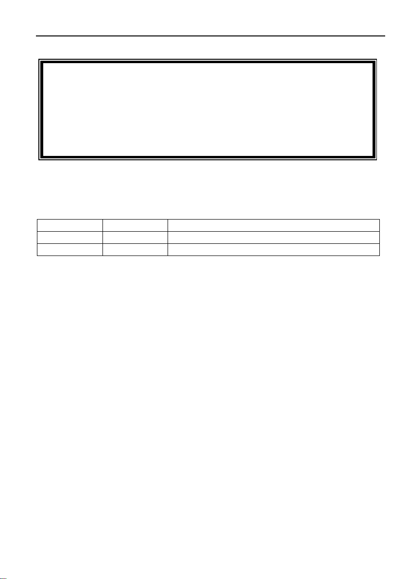
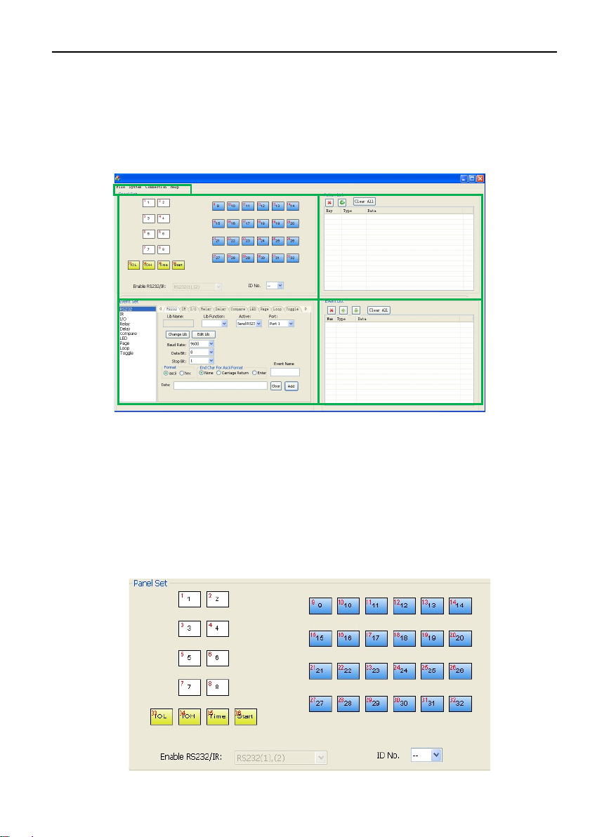
"Programmed by USB or RS232, working with the PC software (PS-WP).
"Crystal and backlit buttons with easy user-friendly customizable changeable labels
"The backlit brightness is controllable
"Mini USB connector
"Décora style wall plate
"Dimensions: 11.4cm long and 7cm wide

Programmable Control Panel
2
3. Specification
Specification
Program Port
USB or RS232
Output Port
3 x RS232, 1 x RS485, 3
x Infrared, 2 x Relay
Serial Control
Port
RS232
Baud Rate
And Protocol
9600 baud, 8 data bits, 1
stop bit, no parity
Software
PS-WP
Temperature
-20 ~ +70°C
Frequency
Response
20Hz ~20KHz
Humidity
10% ~ 90%
Power Supply
100VAC~240VAC,
50/60 Hz
Power
Consumption
1W
Case
Dimensions
114x70 x28mm
Product
Weight
0.15kg
4. Connection Introduction
4.1 Interfaces Introduction
The programmable control panel has various ports in the rear panel, including Lopping
port, RS232 port, RS485 port, IR port, Relay port and Power port. Below is the
introduction:
①This port includes two parts:
One part is RS232 (2)/IR3, it can be used for control other devices or looping
output. RS232 (2) and IR3 share the same port, the detailed use depends on the
setting of PS-WP.

Programmable Control Panel
3
Other part is RS232 (3), it can be used for control other devices or looping output,
or connect with PC.
These two parts share the same grounding.
②This port includes: RS232 (1)/IR2, IR1 and RS485.
a) RS232 (1)/IR2: share the same port; the detailed use depends on the setting of
PS-WP. When be used as RS232, it is unidirectional transmission, transmit
data but without receive.
b) IR1: for control other devices, it can be programmable by the PS-WP.
c) RS485: the RS485 can be programmed as different commands and control the
device with RS485 port. The command of RS485 is the same as RS232 (1).
③Low-Voltage relay ports: set the relay on/off by software PS-WP.
④Power connector: 12VDC. Be sure that the “+” and “-” never be mixed or
wrong connection.
⑤Infrared sensor port: receive and learn the IR code, to build the IR database.
⑥Mini USB Connector:
Communicate with PC, which uses PS-WP to program the buttons.
Transmit the infrared data when learning IR (Optional).
4.2 Connection of Programming and Looping
The programmable control panel can be connected to the computer for programming,
to default the functions of every button. It can be connected by USB or RS232, working
with the PS-WP software. It is shown as below:
Programming Connection
Note: When use this USB port to program the control panel’s buttons, the available
COM port number should not be more than 10.

Programmable Control Panel
4
Several pieces programmable control panels can be also looped to be a system, for
control more devices. It is looped by the inter RS232 setting. Please check the demo
picture as below:
Several programmable control panels Looping connecting
After connect the programmable control panels as above, and then we should set the
ID of each programmable control panel by PS-WP. The ID number is from 01 to 99,
and it also is the class of the programmable control panel in the loop, different
programmable control panels should set to different ID. After connections finish, we
can set the control modes by PS-WP. For detailed connecting, please check the
picture below:
Detailed looping connecting
First class
Second class
Last class …

Programmable Control Panel
5
5. System Operations
5.1 Front Panel Introduction
Crystal and luminescent, programmable buttons:
Every button can be programmable with the software PS-WP.
Connect the PC via USB or RS232.
And every label inside the button can be changeable. You can choose the label you
need and change it very easily like below:
(For the specific transparent paper table, please contact the local distributor or reseller
for it)
5.2 USB Driver Installation
There are USB driver file and PS-WP software in the disk. The PS-WP can run directly
without installation.
But when connect the programmable control panel with PC by USB; it may need to
install the USB driver. Use the driver file to install the driver of USB; we can use USB
to program the programmable control panel.
5.3 Software Programming
You can use this software PS-WP to easily set every button of the programmable
control panel.

Programmable Control Panel
6
After connect the programmable control panel with PC by USB or RS232, we can
open the PS-WP to program the buttons for controlling.
The main window of PS-WP has five parts: main menu, panel (button) setting, event
setting, action list and event list. In this manual we will take WP8-V for example, to
show the uses of all functions.
The main window of PS-WP is as below:
We will introduce all the configurations one by one.
5.3.1 Main Menu
The main menu includes file management, system model, connection type and help.
1) File management: Open/Save/Save as a configuration. After program, user can
save the configuration to a file, so that you can use the same configuration next
time.
2) System model: includes WP8-H, WP8-V, WP19R etc, and the buttons interface
view is different with different models. The pictures below show the differences
between WP8-V and WP8-H.
Table des matières


