K-Rain 3208-UWRFS Mode d'emploi

Universal Wireless
Rain/Freeze Sensor
OWNER’S MANUAL AND
INSTALLATION INSTRUCTIONS
3208-UWRFS

01
TABLE OF CONTENTS
Introduction ...............................................2
Features & Benefits ..........................................3
Universal Rain Sensor Receiver Components ......................4
Rain/Freeze Sensor Components ................................5
Installing the Universal Rain Sensor Receiver into Controllers .........6
With Sensor Terminals ......................................6
Without Sensor Terminals ...................................6
Wiring for all Installation Methods .............................7
Check to verify correct wiring.................................7
Mounting the Universal Rain Sensor Receiver ......................8
Pairing with the Wireless Rain Sensor ............................8
Mounting the Rain Sensor .....................................9
Standard Flat Mounting .....................................9
Gutter Mounting...........................................9
Tips for Mounting..........................................9
Adjustments And Operation ...................................10
Bypassing The Rain Sensor ...................................10
Specifications..............................................11
Troubleshooting ............................................12
FCC Declaration of Conformity ................................13
FCC Notice ................................................14
Warranty .......................................... back cover

www.krain.com 02
INTRODUCTION
Thank you for selecting the K-Rain®Universal Wireless Rain/Freeze Sensor.
The Universal Rain Sensor Receiver allows installation with most irrigation
controllers – regardless of the manufacturer. Once successfully paired with
the K-Rain Wireless Rain/Freeze Sensor, the controller will be able to expertly
manage water efficiency by suspending watering during rain and/or freeze
periods.
After a set amount of rain has fallen and/or freezing temperatures exist, the
sensor will trigger the controller to suspend watering. The freeze sensor
interrupts your sprinklers and reduces the hazards of standing water freezing
on your driveway, sidewalks, and patios when temperatures drop below 37°F
[3°C]. Once the rain sensor has dried sufficiently, the sensor allows normal
sprinkler operation. Works with most new and existing sprinkler systems.
This rain sensor will NOT work with open circuit controllers.
WARNING: Use with 24V AC power only! Connecting this sensor to 120V or
240V AC power may result in severe equipment damage.

03
FEATURES & BENEFITS
Universal Wireless Rain/Freeze Sensor
• Flexibility. The Universal Wireless Rain/Freeze Sensor can be paired
with nearly any manufacturer’s controller, providing a cost efficient
option to add a wireless rain sensor to most irrigation systems.
• The K-Rain Wireless Rain/Freeze Sensor (model 3208-UWRFS) can
be paired with multiple K-Rain Pro EX 2.0 Wifi enabled controllers
within range, providing additional value for the end user.
• Quick Installation and Programming. The Universal Wireless Rain/
Freeze Sensor provides the advantage of extremely quick installation.
• Weather Resistant. Engineered with impact modified, UV resistant
polymer for outdoor exposure.
• Maintenance Free. No batteries to replace.
• 2 in 1 Mounting. Provides flexible installation with standard flat
and gutter mounting.
• Model 3208-UWRFS includes a freeze sensor that prevents the irrigation
system from starting when temperatures drop to 37°F or below.

www.krain.com 04
UNIVERSAL WIRELESS RAIN/FREEZE SENSOR RECEIVER
COMPONENTS
1. Pair Button. Initiates the pairing process.
2.Paired LED. Displays status of pairing to the Wireless Rain Sensor.
The LED will flash green for pairing process, stay green under normal
conditions and turn flashing red after 24 hours from last successful
pairing to indicate connection loss.
3.Suspended LED. Indicates program suspension due to a rain or freeze
event. The LED will be off normally and will turn red whenever a rain or
freeze event occurs.
4.Battery LED. Indicates health of the rain sensor battery. The LED will be
green at good battery health and turn red when battery life is under 10%.
5.Radio Antenna. Receives wireless signal from the rain sensor, up to 300 feet.
6.Wiring Harness. Includes 2 yellow sensor wires, one red 24V AC power
wire and one black common wire.
2. Paired LED
5. Radio Antenna
(internal)
6. Wiring Harness
3. Suspended LED
4. Battery LED
1.Pair Button
05
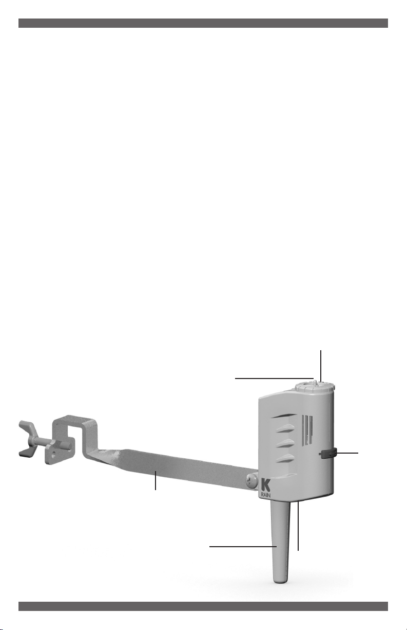
RAIN/FREEZE SENSOR COMPONENTS
1.Manual Test Pin. Press and hold for three seconds to confirm
proper operation.
2.Vent Adjustment Tab. Used to adjust the dry out time of the sensor.
Depending on weather conditions, the farther open the vent windows, the
sooner the unit will dry out and let the controller resume normal operations.
3.Mounting Arm. Metal extension arm for mounting the sensor.
4.Rainfall Adjustment Cap. The rain sensor cap can be adjusted to
suspend watering when rainfall amounts of 1/8" (minimum setting)
through 1/2" or more has fallen.
5.Freeze Sensor. Prevents the irrigation system from starting when
temperatures drop to 37°F or below. When temperatures rise above
37°F, the sensor will enable automatic watering.
6.Radio Antenna. Transmits a wireless signal to the receiver.
NOTE: Unit needs to be mounted with the radio antenna in a vertical position.
7.Battery / Transfer Signal LED. Pressing the Manual Test Pin for three
seconds allows the user to see the LED flashing ON / OFF; indicating that
the battery is functioning and is transmitting the signal to receiver.
1.Manual Test Pin
2.Vent
Adjustment
Tab
3.Mounting Arm
4.Rainfall Adjustment Cap
6.Radio Antenna
5.Freeze Sensor (internal) 7.Battery / Transfer
Signal LED (beside
Radio Antenna)

www.krain.com 06
INSTALLATION
Installing the K-Rain Universal Rain/Freeze Sensor Receiver into
controllers WITH sensor terminals.
Find the controller sensor terminals (generally marked “SENSOR”, “SEN”
or “S”) and attach the yellow Universal Rain Sensor control wires directly to
these terminals in any order. Next install the red power wire to the positive
terminal (generally marked “VT” or “24VAC”) and the black common wire
to the common terminal (generally marked “C” or “COM”) or the neutral
24VAC terminal.
NOTES:
• There may be a jumper tab or wire
between the sensor terminals that
must be removed.
• If a rain sensor is removed, the
preinstalled jumper wire MUST be
reinstalled on the SENSOR terminals.
• Controllers with global overide and/or switch must
be active/on in order for the sensor to work properly.
Installing the K-Rain Universal Rain Sensor Receiver into controllers
WITHOUT sensor terminals.
a. WITHOUT pump start relay/master valve (Fig. 1). Find the controller
common terminal (generally marked “C” or “COM”) and attach one yellow
Universal Sensor wire directly to the terminal. Locate the second yellow
Universal Sensor wire and connect directly to the field common valve wire.
NOTE: The common wire to the valves does not have to be interrupted at the controller.
Rain sensor may be wired anywhere along the common wire line.
Irrigation System Controller
To Valves
Common Wire From Valves
Wire Connector
RED
BLACK
YELLOW
YELLOW
1234
CP
24 VAC SENSOR
FIGURE 1:
Irrigation System Controller
To Valves
RED
BLACK
YELLOW
YELLOW
1234
CP
24 VAC SENSOR

Irrigation System Controller
To Valves
Pump Start Relay/
Master Valve
Common Wire From Valves
Wire Connector
1234
CP
24 VAC SENSOR
RED
BLACK
YELLOW
YELLOW
FIGURE 2:
b. WITH pump start relay/master valve (Fig. 2). Locate the common wire
to the solenoid valves and the common wire lead to the coil of the relay
that starts the pump. If these two wires are connected to the “common”
terminal on the controller, disconnect both of them. Twist these two wires
together along with one yellow wire from the Universal Rain Sensor and
secure with a wire nut. Attach the other yellow wire of the rain sensor to
the “common” terminal on the controller.
WIRING
For all installation methods:
Once the rain sensor receiver is mounted, run the wires to the controller using
wire clips every few feet to fasten it. If an extension to the wires provided is
needed, use the following table to determine the minimum wire gauge needed:
Extension Needed: 25-50 ft. 50-100 ft. 100 ft. or more
Minimum Wire Gauge: 20 AWG 18 AWG 16 AWG
Check to verify correct wiring:
Turn on one zone of the sprinkler system that is visible while you are in
reach of the rain sensor. Manually depress the manual test pin at top of the
rain sensor until you hear the switch “click” off. The sprinkler zone should
stop instantly. If it does not, check wiring for correct installation.
07
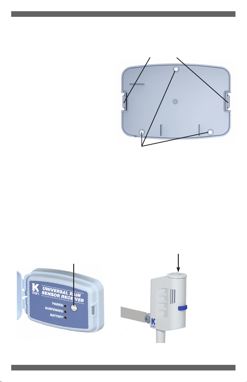
MOUNTING THE UNIVERSAL RAIN SENSOR RECEIVER
• Remove the Back Housing
from the Main Housing using
the side clips shown here.
• Mount the Back Housing
through the 3 mounting
holes utilizing the supplied
hardware (fig.3).
• Once the Back Housing is
installed, attach the Main
Housing with the 2 side
clips (fig.3).
• Take care to ensure the
supplied rubber wiring harness
grommet seals correctly against
the 2 halves of the housing.
PAIRING WITH THE WIRELESS RAIN SENSOR
Press and hold the PAIR button on the Universal Rain Sensor Receiver for
at least 3 seconds until the green PAIRED LED begins flashing rapidly (fig.4).
Next, press and hold the MANUAL TEST PIN on the Wireless Rain/Freeze
Sensor for at least 3 seconds. The PAIRED and BATTERY LEDs will both
display solid in green upon successful pairing (fig.5).
www.krain.com 08
Mounting Holes
Side Clips
FIGURE 4: FIGURE 5:
FIGURE 3:
Pair Button
Manual Test Pin

MOUNTING THE RAIN SENSOR
Standard Flat Mounting
Mount the sensor on a surface
that is unobstructed to rain fall,
but away from the path of the
sprinkler water spray.
Gutter Mounting
Allows the rain sensor to be mounted
directly to the side of the gutter.
Position the gutter mount on the
edge of the gutter and twist the
thumbscrew to secure it in place.
Tips for mounting
a. When looking for a suitable location such as the side of a building or a
post, positioning the Rain Sensor closer to the controller will help to avoid
interference to the wireless signal.
b. Mount in the highest possible position where rain can fall directly upon
the rain sensor.
c. The rain sensor mounting location will affect the reset rate (amount of
time it takes the rain sensor to dry out sufficiently for the sprinkler system
to reactivate). For example, mounting the rain sensor on a very sunny,
southeastern end of a building may cause the rain sensor to dry out
sooner than desired. Similarly, mounting on the northern end of a building
with constant shade may keep the rain sensor from drying out at all.
Some experimentation with the “vent adjustment tab” will usually yield
satisfactory results.
09
Table des matières
Autres manuels K-Rain Accessoires


