Juniper MX240 Manuel utilisateur

MX240 and MX480
Ethernet Services Router
Fan Tray Installation Instructions
13 February 2008
Part Number: 530-022145-01
Revision 1
This document describes how to remove and replace the fan tray on a Juniper
Networks MX240 and MX480 Ethernet Services Router. The fan tray and the air filter
make up the cooling system.
Contents Cooling System ...............................................................................................2
Replacing the Fan Tray ....................................................................................4
Removing the Fan Tray .............................................................................5
Installing the Fan Tray ..............................................................................6
Electrostatic Discharge Point ...........................................................................7
Preventing Electrostatic Discharge Damage ....................................................9
List of Technical Publications ..........................................................................9
Requesting Technical Support .......................................................................16
Revision History ............................................................................................17
■1

Cooling System
The cooling system consists of the following components:
■Fan tray
■Air filter
The cooling system components work together to keep all router components within
the acceptable temperature range (see Figure 1 on page 2, Figure 2 on page 2,
Figure 3 on page 3, Figure 4 on page 3, Figure 5 on page 4, and
Figure 6 on page 4). The router has one fan tray and one air filter that install
vertically in the rear of the router. The fan tray contains three fans on an MX240
router and six fans on an MX480 router.
The air intake to cool the chassis is located on the side of the chassis next to the air
filter. Air is pulled through the chassis toward the fan tray, where it is exhausted out
the side of the system. The air intake to cool the power supplies is located in the
front of the router above the craft interface. The exhaust for the power supplies is
located on the rear bulkhead power supplies.
Figure 1: Airflow Through the MX240 Chassis
Figure 2: Airflow Through the MX480 Chassis
The host subsystem monitors the temperature of the router components. When the
router is operating normally, the fans function at lower than full speed. If a fan fails
or the ambient temperature rises above a threshold, the speed of the remaining fans
is automatically adjusted to keep the temperature within the acceptable range. If the
ambient maximum temperature specification is exceeded and the system cannot
2■Cooling System
MX240 and MX480 Ethernet Services Router Fan Tray Installation Instructions

be adequately cooled, the Routing Engine shuts down the system by disabling output
power from each power supply.
Figure 3: Fan Tray in an MX240 Router
Figure 4: Fan Tray in an MX480 Router
Cooling System ■3
Cooling System

Figure 5: Air Filter on an MX240 Router
Figure 6: Air Filter on an MX480 Router
Replacing the Fan Tray
The router has one fan tray that installs vertically in the rear of the chassis. The fan
tray contains three fans on an MX240 router and six fans on an MX480 router. The
fan tray is hot-removable and hot-insertable.
The fan tray is located in the rear of the chassis on the right side. The fan tray weighs
about 6.8 lb (3.08 kg).
NOTE: To prevent overheating, install the replacement fan tray immediately after
removing the existing fan tray.
4■Replacing the Fan Tray
MX240 and MX480 Ethernet Services Router Fan Tray Installation Instructions
To replace the fan tray, use the following procedures:
■Removing the Fan Tray on page 5
■Installing the Fan Tray on page 6
Removing the Fan Tray
To remove the fan tray (see Figure 7 on page 5 and Figure 8 on page 6):
1. Attach an electrostatic discharge (ESD) grounding strap to your bare wrist and
connect the strap to one of the ESD points on the chassis. For more information
about ESD, see “Preventing Electrostatic Discharge Damage”on page 9.
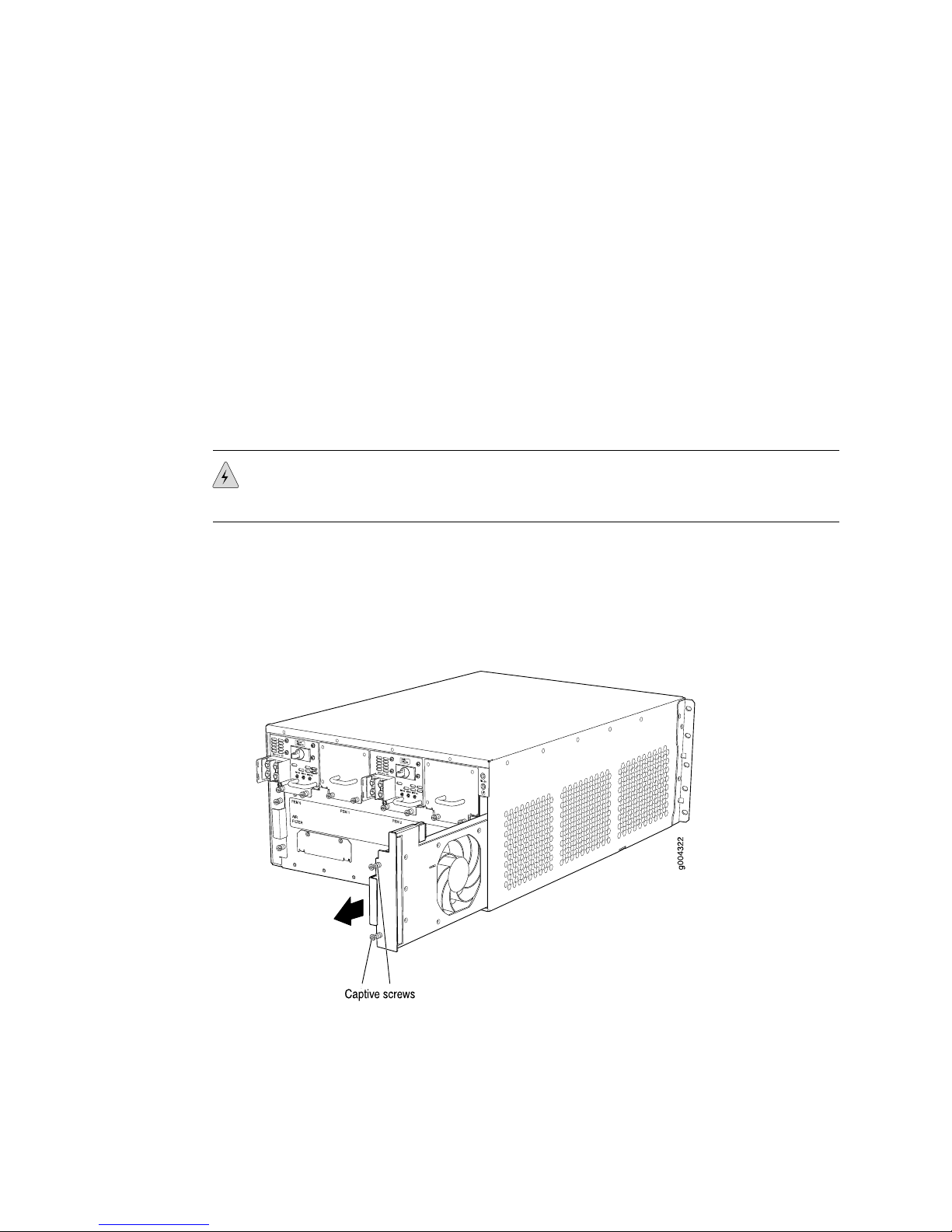
2. Loosen the captive screws on the fan tray faceplate.
3. Grasp the fan tray handle and pull it out approximately 1 to 3 inches.
WARNING: To avoid injury, keep tools and your fingers away from the fans as you
slide the fan tray out of the chassis. The fans might still be spinning.
4. Press the latch located on the inside of the fan tray to release it from the chassis.
5. Place one hand under the fan tray to support it and pull the fan tray completely
out of the chassis.
Figure 7: Removing the Fan Tray from an MX240 Router
Replacing the Fan Tray ■5
Replacing the Fan Tray

Figure 8: Removing the Fan Tray from an MX480 Router
Installing the Fan Tray
To install the fan tray (see Figure 9 on page 7 and Figure 10 on page 7):
1. Attach an electrostatic discharge (ESD) grounding strap to your bare wrist and
connect the strap to one of the ESD points on the chassis. For more information
about ESD, see “Preventing Electrostatic Discharge Damage”on page 9.
2. Grasp the fan tray handle and insert it straight into the chassis. Note the correct
orientation by the this side up label on the top surface of the fan tray.
3. Tighten the captive screws on the fan tray faceplate to secure it in the chassis.
6■Replacing the Fan Tray
MX240 and MX480 Ethernet Services Router Fan Tray Installation Instructions

Figure 9: Installing the Fan Tray in an MX240 Router
Figure 10: Installing the Fan Tray in an MX480 Router
Electrostatic Discharge Point
Figure 11 on page 8 and Figure 12 on page 8 show the location of the ESD point
on the rear of the chassis. The illustration shows a DC-powered router, but the location
is the same in AC-powered routers.
Electrostatic Discharge Point ■7
Electrostatic Discharge Point

Figure 11: Rear View of a Fully Configured DC-Powered MX240 Router
Figure 12: Rear View of a Fully Configured DC-Powered MX480 Router
8■Electrostatic Discharge Point
MX240 and MX480 Ethernet Services Router Fan Tray Installation Instructions

Preventing Electrostatic Discharge Damage
Many router hardware components are sensitive to damage from static electricity.
Some components can be impaired by voltages as low as 30 V. You can easily
generate potentially damaging static voltages whenever you handle plastic or foam
packing material or if you move components across plastic or carpets. Observe the
following guidelines to minimize the potential for electrostatic discharge (ESD)
damage, which can cause intermittent or complete component failures:
■Always use an ESD wrist strap or ankle strap, and make sure that it is in direct
contact with your skin.
CAUTION: For safety, periodically check the resistance value of the ESD strap. The
measurement should be in the range of 1 to 10 Mohms.
■When handling any component that is removed from the chassis, make sure the
equipment end of your ESD strap is attached to one of the ESD points on the
chassis, which are shown in Figure 11 on page 8 and Figure 12 on page 8.
■Avoid contact between the component and your clothing. ESD voltages emitted
from clothing can still damage components.
■When removing or installing a component, always place it component-side up
on an antistatic surface, in an antistatic card rack, or in an electrostatic bag (see
Figure 13 on page 9). If you are returning a component, place it in an
electrostatic bag before packing it.
Figure 13: Placing a Component into an Electrostatic Bag
List of Technical Publications
Table 1 on page 10 lists the software and hardware guides and release notes for
Juniper Networks J-series, M-series, MX-series, and T-series routing platforms and
describes the contents of each document. Table 2 on page 14 lists the books included
in the Network Operations Guide series. Table 3 on page 14 lists the manuals and
Preventing Electrostatic Discharge Damage ■9
Preventing Electrostatic Discharge Damage

release notes supporting JUNOS software with enhanced services. All documents are
available at http://www.juniper.net/techpubs/.
Table 4 on page 15 lists additional books on Juniper Networks solutions that you can
order through your bookstore. A complete list of such books is available at
http://www.juniper.net/books.
Table 1: Technical Documentation for Supported Routing Platforms
DescriptionBook
JUNOS Software for Supported Routing Platforms
Explains how to configure access privileges in user classes by using
permission flags and regular expressions. Lists the permission flags
along with their associated command-line interface (CLI) operational
mode commands and configuration statements.
Access Privilege
Provides an overview of the class-of-service (CoS) functions of the
JUNOS software and describes how to configure CoS features,
including configuring multiple forwarding classes for transmitting
packets, defining which packets are placed into each output queue,
scheduling the transmission service level for each queue, and
managing congestion through the random early detection (RED)
algorithm.
Class of Service
Describes how to use the JUNOS command-line interface (CLI) to
configure, monitor, and manage Juniper Networks routing
platforms. This material was formerly covered in the JUNOS System
Basics Configuration Guide.
CLI User Guide
Provides a detailed explanation and configuration examples for
several of the most complex features in the JUNOS software.
Feature Guide
Provides an overview of hardware and software resources that
ensure a high level of continuous routing platform operation and
describes how to configure high availability (HA) features such as
nonstop active routing (NSR) and graceful Routing Engine
switchover (GRES).
High Availability
Provides an overview of traffic engineering concepts and describes
how to configure traffic engineering protocols.
MPLS Applications
Provides an overview of multicast concepts and describes how to
configure multicast routing protocols.
Multicast Protocols
Describes how you can deploy IPTV and voice over IP (VoIP)
services in your network.
Multiplay Solutions
Describes common configuration scenarios for the Layer 2 features
supported on the MX-series routers, including basic bridged VLANs
with normalized VLAN tags, aggregated Ethernet links, bridge
domains, Multiple Spanning Tree Protocol (MSTP), and integrated
routing and bridging (IRB).
MX-series Solutions Guide
Provides an overview of the network interface functions of the
JUNOS software and describes how to configure the network
interfaces on the routing platform.
Network Interfaces
10 ■List of Technical Publications
MX240 and MX480 Ethernet Services Router Fan Tray Installation Instructions
Autres manuels pour MX240
9
Ce manuel convient aux modèles suivants
1
Table des matières
Autres manuels Juniper Accessoires


