JOYTECH PY600AC Manuel utilisateur

PY600AC
Sliding Gate Opener
User Manual
2017

1
Dear users,
Thank you for choosing this product. Please read the manual carefully before assembling and using it.
Please do not leave out the manual if you send this product to a third party.
1. Safety Instruction
Please ensure that the using power voltage matches with the supply voltage of gate opener
(AC110V or AC220V); kids are forbidden to touch the control devices or the remote-control unit.
The remote-control unit is controlled by a single button mode or three button mode (please refer to
the instructions of the remote control in accordance with the actual gate opener type). The indicator
light on the remote-control unit will flicker when the button on it is pressed. Main engine and gate can
be unlocked by disengagement wrench and the gate can move with manual operation after
disengagement.
Please ensure that no one is around the main engine or gate when the switch is operated and it is
usually demanded to examine the stability of installation. Please temporarily stop using if the main
engine needs repairing or regulation.
The installation and maintenance of the products must be carried out by professionals.

2
2. Packing List (standard)
No.
Picture
Name
Quantity
1
Main engine
1
2
Manual release key
2
3
A
B
C
D
A
B
C
D
Remote control
2
4
Spring limit switch
accessories box / Magnetic
limit switch accessories box
1
4-1
or
Spring limit switch block
/ Magnetic limit switch block
1
4-2
Foundation bolt M8
4
4-3
Limit switch block mounting
screw M6X18
4
4-4
Nut M8
8
4-5
Flat washer Ø8
8
4-6
Spring washer Ø8
4
3
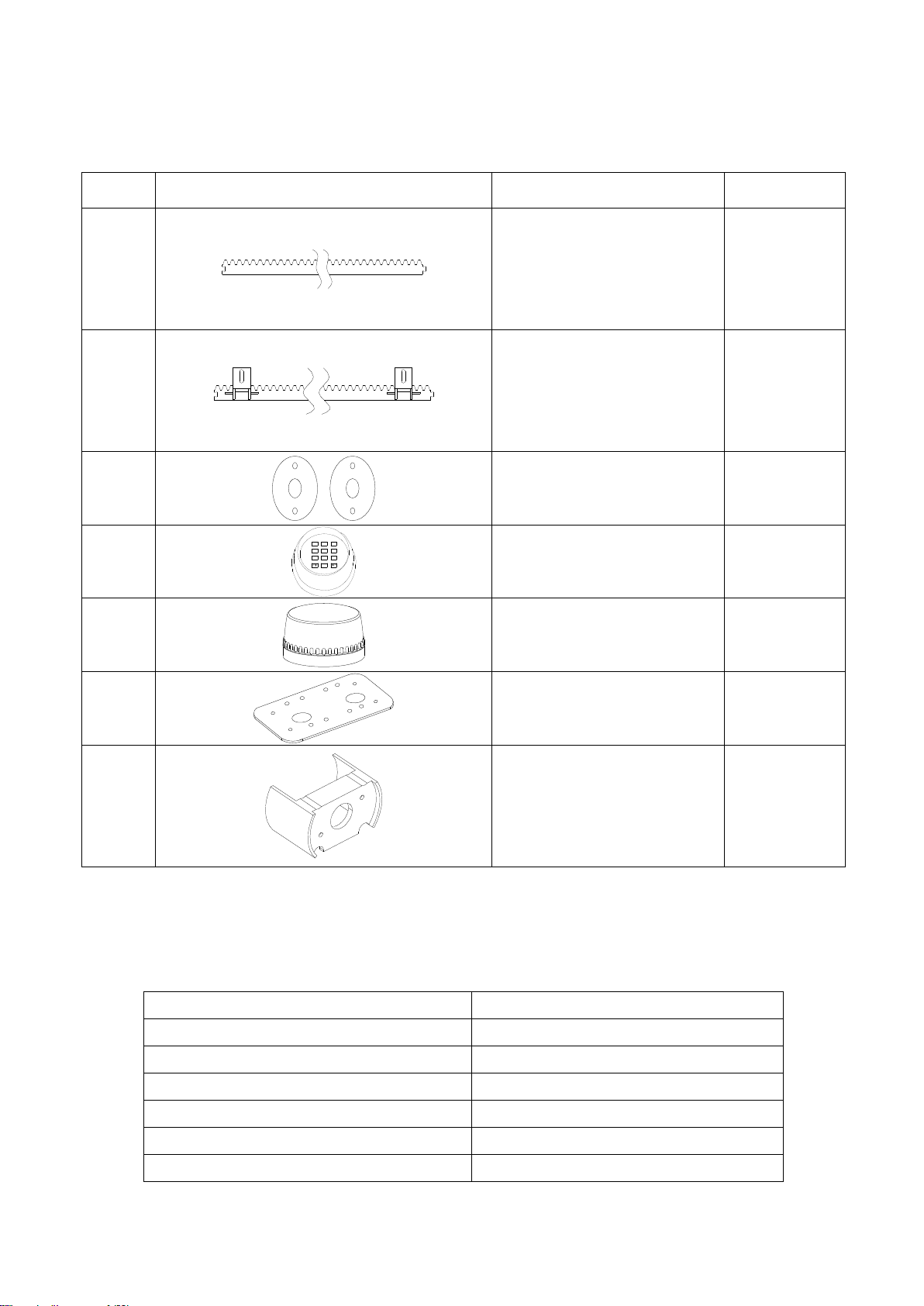
2. Packing List (optional)
No.
Picture
Name
Quantity
1
Steel gear rack
1m/pc
2
Nylon gear rack
1m/pc
3
Infrared sensor
1
4
0
8
5 6
97
4
1 2 3
Wireless keypad
1
5
Alarm lamp
1
6
Mounting plate
1
7
Protect cover for output gear
1
3. Technical parameters
Model
PY600AC
Power supply
220V/50Hz;110V/60Hz
Motor power
280W
Gate moving speed
13m/min
Maximum weight of gate
600Kg
Remote control distance
≥30m
Remote control mode
Single button mode

4
/ Three button mode
Limit switch
Spring limit switch
Magnetic limit switch
Noise
≤58dB
Working duty
S2, 15min
Recording of up remote controls
25
Frequency
433.92 MHz
Working temperature
-20°C ~ +70°C
Package weight
9.4Kg
4. Installation
PY600AC sliding gate opener is applicable to gate weight less than 600kg, and length of the sliding
gate should be less than 12m. The drive mode adopts the gear and rack transmission. This gate
opener must be installed inside the enclosure or yard for protection.
4.1 Installation drawing
⑤
④
③
②
0
8
5 6
97
4
1 2 3
⑧
①
⑦
⑥
Figure 1
①Gate opener; ②Wireless keypad (optional); ③Gate; ④Infrared sensor (optional);
⑤Alarm lamp (optional); ⑥Safety stop block; ⑦Gear rack; ⑧Remote control;
4.2 Size of main engine and accessories
4.2.1 Size of main engine

5
241
260
217
Figure 2 (1) Spring Limit Switch
260
241 213
Figure 2 (2) Magnetic Limit Switch
4.2.2 Size of mounting plate
107
150
204±0.3
90±0.3
Figure 3

6
4.3 Installation procedures
4.3.1 Preparation work before installation
Please ensure that the sliding gate is correctly installed, the gate rail is horizontal, and the gate can
glide back and forth smoothly when moved by hands before installing the gate opener.
Cable installation
Please bury the motor & power cable and controlling cable with PVC tube, and use two PVC tubes
to bury (motor & power cable) and (controlling cable) separately, so as to guarantee normal
operation of the gate opener and protect the cables from damages.
Concrete pedestal
Please cast a concrete pedestal with the size of 400mm x 250mm and depth of 200mm in advance,
so as to firmly install PY600AC gate opener. Please verify whether the distance between the
gate and gate opener is suitable before casting the pedestal.
Embedded screws
Concrete
Power line
Mounting plate
Foundation bolt
Figure 4
4.3.2 Main engine installation
a) Dismantle the plastic housing on the main engine before installation and keep relevant fasteners
properly;
b) Please prepare the power line for connecting mounting plate and main engine (the number of
power supply cable core shall not be less than 3 PCS, the sectional area of cable core shall not be
lower than 1.5mm²and the length shall be determined by users according to the field situation) due
to different installation environments;
c) Please unlock the main engine before installation, the unlock method is: insert the key, open the
manual release bar till it rotates by 90°as shown in Figure 5. Then turn the output gear and the gear
can be rotated easily;

7
Turn on 90°
Figure 5
4.3.3 Gear rack installation
Fix the mounting screws to the rack.
Put the rack on the output gear, and weld the mounting screw to the gate (each screw with one
solder joints firstly).
Unlock the motor and can pull the gate smoothly.
Please check whether there is a fit clearance between rack and output gear, as shown in Figure
7.
Weld all the mounting screws to the gate firmly.
Make sure that all racks on the same straight line.
Pull the gate after installed, make sure the entire trip is flexible no stuck.
Figure 6
The fit clearance of output gear and rack is shown in Figure 7 below:
1-21-2
GearGear rackrack
OutputOutput geargear
mmmm
Figure 7

8
Warnings
·To ensure safety, install safety stop blocks on both ends of the rails to prevent the gate out of the rail.
Before installing the main engine, make sure that the safety stop blocks are in place and whether it
has the function of preventing the gate from moving out of the rail and out of the safety range.
·Please ensure that the main engine and its components have good mechanical properties, and the
gate can operate flexibly when moved by hands before installing the main engine.
·In this product, one control can drive one main engine only, otherwise, the control system will be
damaged.
·Earth leakage circuit breaker must be installed where the gate movement can be seen, and the
minimum mounting height is 1.5m to protect it from being touched.
·After installation, please check whether the mechanical property is good or not, whether gate
movement after manual unlocking is flexible or not, and whether the infrared sensor (optional) is
installed correctly and effectively.
4.3.4 Limit switch adjustment
Spring limit switch - The installation site of spring limit switch is shown in Figure 8:
GateGate
SpringSpring limitlimit switchswitch
SpringSpring limitlimit switchswitch stopstop blockblock
GearGear rackrack
OutputOutput geargear
Figure 8
The installation of spring limit switch stop block is shown in Figure 9:
M6×18M6×18 M6×18M6×18
Figure 9

9
Magnetic limit switch - The installation site of magnetic limit switch is shown in Figure 10:
GateGate
MagnetsMagnets
MagneticMagnetic limitlimit switchswitch stopstop blockblock
GearGear rackrack
OutputOutput geargear
≤20mm
Figure 10
The installation of magnetic limit switch block is shown in Figure 11:
M6×18M6×18 M6×18M6×18
Left side mounting Right side mounting
Figure 11
Note: The default setting is right side mounting. (According to actual situation, please refer to the
“Note”of section 4.3.5.1 and 4.3.5.2 “Adjustment and operation”to adjust.)
Table des matières
Autres manuels JOYTECH ouvre-porte de garage

Manuels ouvre-porte de garage populaires d'autres marques


Craftsman
Craftsman 139.53924 Manuel utilisateur

Chamberlain
Chamberlain MyQ 940ESTD Manuel utilisateur

Automatic Technology
Automatic Technology GDO-9V1 SecuraLift Manuel utilisateur

Westfalia
Westfalia 19 36 07 Manuel utilisateur

Chamberlain
Chamberlain HD520EVP Manuel utilisateur

Cardin
Cardin BL Series Manuel utilisateur