FORM 145.20-IOM1 (908)
9
JOHNSON CONTROLS
4. UNPACKING
a) Check the unit for indications of damage in ship-
ment. Notify the Transportation company of any
damage and note the damage on the shipping
receipt.
Rough handling may dislocate internal
components.
b) Allow the shipping base to remain with the unit
until it is ready to be set in its nal location.
c) Rotate blowers to assure free movement.
d) The compressor is mounted on neoprene isolators
with metal spacing sleeves inside and secured with
nuts, which must be snug against the metal spacer
sleeves.
e) Check all refrigeration tubing to assure that it does
not rub against any other parts.
5. NORMAL INSTALLATION
This unit is designed for indoor installation adjacent
to an outside wall having an opening for outdoor air
ow. The air ow products must:
a) Discharge directly to the outside.
b) Discharge away from any obstructions which could
cause discharged air recirculation.
6. CLEARANCES
The unit is design certied for closet installation with
the minimum clearances to combustible materials as
stated on the data label. No clearance is required
from the top, sides, or back of the unit. A minimum
of 1 inch clearance is required from the front to any
combustible materials. A combustible door may be
placed 6 inches from the front of the unit. When the
door is open there must be 30 inches clearance to
any obstruction, to allow sufcient access for service
and the replacement of parts.
Outside Wall Thickness 5”-8”
D = (29” – B)
Outside Wall Thickness 8”-12”
D = (33” – B)
Outside Wall Thickness 12”-15”
D = (36” – B)
7. WALL OPENING
A nished opening in an outside wall is required
for intake and exhaust of outdoor airow. The wall
opening required is 21-3/4” wide by 44” high. The
bottom edge of wall opening must be located at least
6” higher from nished oor
Consult local ordinances for building opening fram-
ing requirements.
8. WALL SLEEVE
A factory-made wall sleeve is required to nish
the wall opening. The sleeve should be positioned
with a minimum of ¼” protruding from the nished
outside wall face. This projection allows installation
of the exterior grille without interference from the
exterior nishing materials, and provides a right
angle surface to apply a caulking bead around the
wall penetration.
Use a spirit level or plumb line to make sure that the
wall sleeve vertical anges, which must mate with the
back of the unit, are perfectly vertical. The sleeve
must be secured to the building framing with suitable
eld-supplied fasteners (i.e. lag screws). (NOTE:
Use shims as necessary, between the sleeve and
the rough wall opening, to compensate for any ir-
regularities at the sleeve fastening locations.) DO
NOT allow the fasteners to distort the wall sleeve
side panels.
A roll of ¾” wide x ½” thick self adhesive foam gasket
is packed in the blower compartment of the unit, to
be used for sealing between the wall sleeve and the
unit. Before moving the unit into nal position, apply
self-adhesive foam gasket to all the mating anges
on the wall sleeve, be sure to apply gasket material
to the divider panel ange between the top and bot-
tom sections of the wall sleeve. Also apply gasket
material to the vertical ange of fresh air divider.
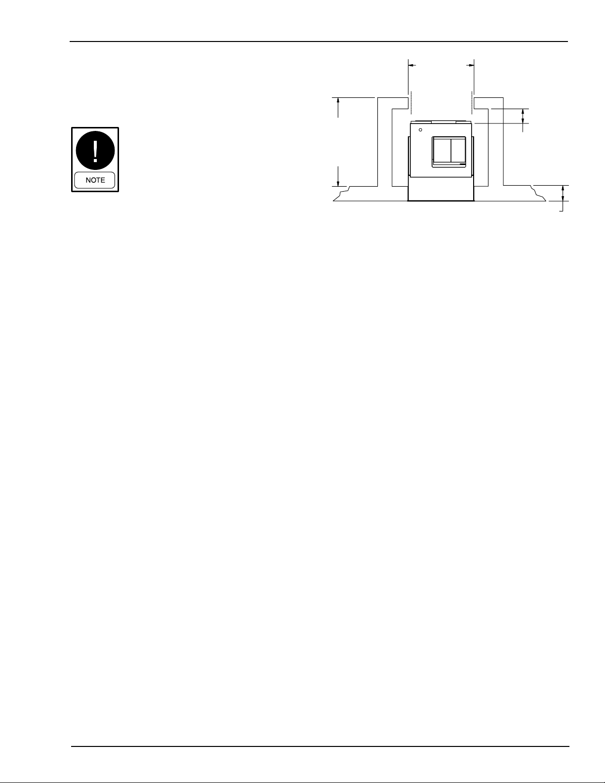
22" min.
clear opening
Line up Unit
with door openning
3" min.
recommended
"D"
Closet Depth
"B"
LD13500