Jets Munt VT80BL Manuel utilisateur

VT80BL Instruction Manual
VT80BL Instruction Manual Page 1
Specifications:
Nominal thrust: 80N at 150.000 RPM
Idle thrust: 4,5N
Idle RPM: 45,000
Diameter: 90,5mm (3.56”)
Engine weight: 950g (2.1lb)
Installed weight: 1,075g (2,37lb)
Fuel: Kerosene + 3% - 5% oil
Fuel comsumption: 220g/min
Start mode: Direct Kerosene
JETS MUNT S.L

Torrent d’en Puig, 31.08358, Arenys de Munt, BARCELONA,Spain
Tel/Fax: +34 93 7950113
www.jetsmunt.com
E-mail: [email protected].
© Copyright 2012, Jets Munt SL. All Rights Reserved
JETS MUNT S.L
INDEX
VT80BL Instruction Manual Page 2
JETS MUNT S.L
Welcome.................................................................................................Page 3
Legal and Disclaimer..............................................................................Page 3
Disclaimer...............................................................................................Page 3
Warranty.................................................................................................Page 4
Safety Notes...........................................................................................Page 5
Engine Description.................................................................................Page 6
Installation Notes....................................................................................Page 6
Electronic Control Unit (ECU)................................................................Page 7
Smart Data terminal...............................................................................Page 7
Engine installation: Electrical connections.............................................Page 7
Engine installation: Fuel system............................................................Page 8
Fuel filter................................................................................................Page 8
ECU (Engine Control Unit) Set Up........................................................Page 8
Aligning transmitter with ecu.................................................................Page 10
Failsafe.................................................................................................Page 11
Preparing the engine for running..........................................................Page 11
Prevent flood engine............................................................................Page 12
First engine runs..................................................................................Page 12
Priming the fuel system.......................................................................Page 13
Starting the engine..............................................................................Page 13
Engine shut down procedure..............................................................Page 13
WHAT TO DO IN THE CASE OF AN EMERGENCY..........................Page 14
List of ECU message codes................................................................Page 14
Diagnoses...........................................................................................Page 15
Diagnosis messages...........................................................................Page 15
VT80BL Trouble Shooting...................................................................Page 15
Other useful information and installation tips
Fuel System.........................................................................................Page 16
Fuel and Oil..........................................................................................Page 17
Feed Pipes...........................................................................................Page 17
Extra ECU functions.............................................................................Page 18
Maintenance.........................................................................................Page 19
Running Time Counters........................................................................Page 19
Autorestart Function.............................................................................Page 20
Smart Data Terminal.............................................................................Page 23
Welcome!
Congratulations on the purchase of your new Jets Munt VT80 gas turbine engine. Jets Munt
are dedicated to the design and production of engines to the highest standards of quality
and reliability to bring you the customer the very latest next generation engine designs.
The VT80 is the result of an intensive effort of design and tests by the Jets-Munt staff.
During the development period we made extensive use of the latest Computational Flow
Dynamics programs allowing us to optimise the engine performance characteristics.
PLEASE READ!
The Jets Munt SL responsibility is limited exclusively to the repair of the engine and
accessories which are outlined in the conditions of warranty.
Before unpacking the engine please read the manual, and agree to the conditions of
warranty.
Customer satisfaction is important to Jets Munt SL. Technical support is available trough
your local dealer and trough email.
Jets Munt S.L
Torrent d’en Puig 31
08358 Arenys de Munt
Barcelona. Spain
Web site: www.jets-munt.com
E-mail: [email protected]
Fax: +34 93 7950113
Legal and Disclaimer
The engine design and the contents of this manual are copyright by Jets Munt SL, Arenys
de Munt, Barcelona, Spain. All rights reserved.
This manual, the pictures and data are property of Jets-Munt and cannot be used or
reproduced in any way without written permission from Jets Munt SL.
Disclaimer
The VT80BL engine is a sophisticated piece of machinery. Care should be taken at all times
when using the engine. It should only be operated by those with the appropriate skills and
knowledge to do so. This engine is not a toy. Incorrect operation or misuse can cause
damage to property and bodily harm operators, spectators and animals. Jets Munt SL
accepts no liability for any kind of damage which may occur.
Jets Munt SL assumes no responsibility for any errors contained in this document and is not
liable for any damages resulting from such errors.
It is forbidden the use of this engine outside Radio Control applications,
specially those that power vehicles that carry people.
JETS MUNT S.L
VT80BL Instruction Manual Page 3

VT80BL Instruction Manual Page 4
JETS MUNT S.L
Warranty
The warranty period for the VT80 is 2 years from the date of purchase, or 25 running
hours, whichever comes first. Warranty is valid solely for the original owner and is non
transferable upon resale.
Warranty includes all supplied parts, and is limited to manufacturing and material defects
only. Shipment costs, including packing and customs fees are not covered by the warranty
and will be always at owner expense.
Damage or defective operation covered under the warranty terms will be repaired and
tested at no cost the original owner (other than shipping expenses). Repairs not covered
under the terms of warranty will be carried out by Jets Munt SL or their appointed agents
after agreement of costs.
Before returning the engine or ancillary equipment for service of repair, please contact
first to your local dealer or Jets Munt central office to agree action and costs.
Please do not disassemble this engine or any other item supplied. You will breach your
warranty agreement and you will find it is a precision assembly which you will be unlikely to
re-assemble without considerable difficulty and specialist equipment. Simply slackening the
spinner nut of the rotor will immediately lose the delicate balance condition, without which
the engine may not run without damage to its rotating assembly.
This warranty is void if any one or more of the following conditions applies. In such a case
Jets Munt will accept no responsibility for any damage or any other consequence caused by
the VT80 operation.
1. The product has been subject to any form of operation whilst containing incorrect fuel,
oil, or fuel/oil mix.
2. The product is crash damaged, pump is blocked due dirt ingestion, electronics or pump
are flooded by fuel, connection leads are cut or lost its isolation and short-circuit, reverse
polarity on battery, etc.
3. Unauthorized maintenance or modifications have been made to any part of the product,
including the unlocking of the ecu and changing the manufacturer settings or any of the
items supplied has been dissasembled.
4. Parts have been damaged by ingestion of foreign objects (e.g. wires, sand, water etc).
5. The engine has been operated incorrectly.
6. The product has been misused, neglected or inadequately maintained.
7. Damage to the engine where blockages in the fuel system have occurred by unfiltered or
contaminated fuel.
Jets-Munt Representatives:
Check the current dealer list on our web page, www.jetsmunt.com

VT80BL Instruction Manual Page 5
JETS MUNT S.L
Safety Notes
Please remember the engine is not a toy and has the potential to cause bodily harm to you
and others if misused. The VT80 is a sophisticated piece of machinery and should be
treated with a high level of safety when it is in operation.
The following guidelines should be read carefully and adhered to.
1. Always keep a CO2 or similar fire extinguisher of at least 2Kg of CO2 contents close
when starting and operating the engine
2. Always protect eyes and ears during the starting procedure.
3. Be aware of the extreme intake suction hazard, we advise the use of a suitable
commercial wire mesh Foreign Object Damage guard to protect the engine intake. Ensure
you have no loose items of clothing (ties, etc.) or equipment which can readily be sucked into
the engine intake, even from adjacent to the engine.
4. Always operate your engine in open air away from confined spaces as the engine exhaust
contains gases which can cause asphyxiation and nuisance smells.
5. Do not touch the engine whilst it is running. Turbines rotate at a very high rpm and the
engine casing and exhaust can reach very high temperatures. Ensure anything affected by
heat is kept well clear of the engine and exhaust during operation.
6. Never use the engine near to sources of flammable gases, liquids or materials.
7. Keep unauthorized persons, spectators, children and animals well away from the starting
area (at least 30ft or 10 meters away).
8. Always handle turbine fuel and oil with care as they are highly flammable. Store them in
appropriate labeled containers. Never dispose inappropriately. We recommend the use of
suitable disposable protective gloves for the mixing of turbine oil/fuel.
VT80 Specifications
Dimensions: Outer Diameter 90mm; Length: 240mm
Weight: 950grams (engine only). 1075gr including pump and mountingstrap
Nominal thrust @ 15C and sea level: 80N
Max.RPM: 150,000 rpm
Idle RPM: 45,000 rpm
Idle thrust 4N (0.8lbf)
EGT @ max rpm 550-650 ºC
Fuel consumption 0.29 l/min at 80N
Fuel/ oil: Kerosene + 4% Oil See page 17 for oil types and percentages

VT80BL Instruction Manual Page 6
JETS MUNT S.L
Engine Description
The engine is a turbojet of a single shaft design specifically designed to power RC aircraft.
The engine starts automatically thanks to an installed electric starter situated in the front.
The starting sequence is controlled by an electronic unit that initiates the starting
sequence and controls the parameters of the engine within the design limits.
The engine uses a system of direct liquid preheating, ignited by a long life ceramic glow
plug
situated inside the engine. After the initial preheat the liquid fuel is gradually introduced.
The fuel should contain a small percentage of oil and uses part of this fuel to lubricate its
two ceramic high speed bearings.
The fuel for the engine is provided from a fuel tank through a small electrical pump. The
engine speed between idle and maximum is controlled by varying the speed of the fuel pump
through an electronic controller called an ECU (electronic control unit), that is contained
inside the engine.
Installation Notes
1. The engine should be mounted using the strap mount supplied or an approved equivalent.
2. The signal cables from the engine must be carefully routed away from the engine intake
so there is no possibility of accidental ingestion of the wire.
3. Fuel pipe should be routed similarly clear of the intake.
4. The fuel pump should be preferably mounted with the spindle in the vertical position with
the motor uppermost. In the event of any fuel seeping from the pump this will not pass
through the electric motor. Note the pump is supplied fitted with built in suppression filter
to reduce radio frequency noise.
5. The centre of the fuel tank should be mounted laterally, as near to the centre of gravity
(CofG) of the model as possible. This will minimize the CofG shift as the fuel is used during
flight.
6. Any air ducting to the inlet of the engine must have sufficient diameter of at least twice
of the engine intake diameter.
7. If an extended exhaust duct is required, it should be of sufficient diameter and strength
for optimum engine performance.
8. Extreme care should be exercised to ensure that no foreign object, loose parts of the
model or debris are allowed to enter the compartment where the engine is installed.
We recommend testing the engine on a test stand prior airframe installation.
You should have a clear idea of how to arrange the components needed to run the engine
inside the model. The main issue is the fuel tank, you will need to arrange the CofG in the
centre of the tank and adjust the receiver and ECU batteries to achieve the correct
location.
VT80BL Instruction Manual Page 7
JETS MUNT S.L
Electronic Control Unit (ECU)
The ECU integrated inside the engine is custom designed for the VT80 engine and must not
be changed for any other, as this may result in improper control of the engine. Your engine
has been set up and run with this ECU at the factory and the settings should be left as
default. The ECU plugs into your receiver throttle channel and is powered from the receiver
rechargeable battery. The ECU is pre-programmed and only requires simply setting to your
radio.
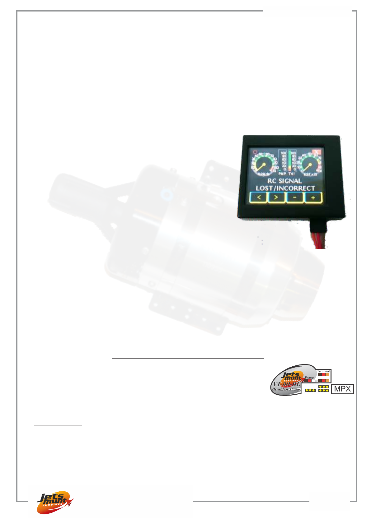
Smart Data terminal
The Smart Data terminal plugs into the ECU via the
lead supplied. The display can be installed permanently
on board. This socket also doubles as digital connection
to a computer.
The Smart Data terminal includes dedicated screens for
radio checking, last shutdown cause and other special
turbine operations. The most innovative and useful
function is the internal recorder/playback function. The
terminal continuously stores all the data received from
the ecu, keeping in its permanent memory all the data of
last 66 minutes of engine run, without the need of the
memory card. After the flight, the terminal can be pulled
out of the plane and, without connecting to the ecu, just
using an 5-10V battery, the data stored can be played
back in real time, same presentation as if the engine was
running. Playback mode can be still, forward or reverse, speed x1, x 10 and x100 in both
directions, so that would be easy to investigate any issue at the field without the need of a
computer or any other type of reader.
Data, including all engine parameters, can be saved later to a memory card, where it can be
read using a text editor, or our viewer software. Also can be sent to engine manufacturer to
be studied, and changes uploaded back to the ecu.
Check the instructions on page 23. The function of the buttons is described later in the
“ECU setup”.
Engine installation: Electrical connections.
Connect the battery to the Multiplex socket “MPX”, connect the
throttle channel from your receiver to the socket “Throttle”, connect
the brushless pump to the socket “Pump” and the smart data terminal
to the socket “Terminal”.
PLEASE: DOUBLE CHECK THE BATTERY POLARITY BEFORE CONNECTING IT TO
THE ENGINE.
A reverse polarity connection will immediately damage the electronic components inside the
engine.
Recommended battery is a LiPo of 7,4V and at least 2000mAh /15C. Optionally is possible
to use an A123 battery of 9,9V, although the engine is happier with 7,4V. 3s Lipo is not
supported.
Throttle

VT80BL Instruction Manual Page 8
JETS MUNT S.L
Engine installation: Fuel system
Install the fuel system components as seen in the picture:
Connect the fuel pump to the ecu. Check the colors. If connector is placed reversed, the
pump will run backwards.
Pump: Note that the fuel pump has an arrow engraved in the front face indicating the
direction of the fuel flow.
Never disassemble the fuel pump, warranty from pump manufacturer will become void.
Fuel filter
The fuel filter must be installed close to the input port on the pump to prevent any particle to
enter in the pump and to damage it. Use a suitable length of the 4mm clear tubing supplied,
keep the tubing on the suction side as short as possible. Direction of flow inside the filter is
not important, but should be always the same after first use.
Do not run the engine without the fuel filter.
Finally connect the fuel pump engine as shown. The fuel pump is a delicate element,
dropping it on the floor can damage it, always handle with care and install using the provided
mount, leave the motor part loose so that it don’t move in respect to the pump part.
It is strongly recommended that, after a new installation or modification on the fuel
system, to disconnect the fuel hose from the engine, routing it to a appropriate container,
and run the pump few seconds using the “pump test function” on the ecu so that some fuel
clean all the possible dirt particles that could have entered in the system during installation.
ECU (Engine Control Unit) Set Up
The ECU supplied is supplied programmed for the VT80. The engine has already been set
up and tested using the same ECU and pump supplied so there is very little to adjust in order
to get the engine running. Confirm you have connected the ECU input to the throttle channel
of your receiver, DISCONNECT the ecu battery, and connect the Data Terminal into the
ECU. Remove all rates, mixes and throttle travel settings in the transmitter. Before doing
any adjustment on the ecu, check that your transmitter is sending the correct signal by
checking the reading of “Pulse” in the data terminal. I should be between 900-1050uS at
STOP, position, between 1100 and 1300uS at IDLE position and between 1800 and 2200 at
Full Power position. Please note that these readings on the ecu are measured directly from
the signal received from your RC system, so you should readjust your transmitter if the
values read are outside that the ones suggested.
The setup assumes the use of a transmitter with manual trims.
If you use a TX with digital trims, is essential to use the switch in the TX
programmed for the function "Throttle cut", or “engine cut” which normally has the
effect of producing the “trim-down” function. Using a digital trim cause unstable idle,
and excessive delay in shutting off the engine in emergency.
Check your radio manual for this before you start. DO NOT use the digital trim in any
case.

VT80BL Instruction Manual Page 9
JETS MUNT S.L
Engine installation: Electrical connections.
Engine installation: Fuel system

VT80BL Instruction Manual Page 10
JETS MUNT S.L
Aligning transmitter with ecu
As the display does not photograph well we have reproduced
the display readings as a green box.
Turn on the transmitter and receiver. The opening screen should
show as (1):
Note there are four buttons on the display, two on the left and
two on the right hand side. The left buttons move to the different
screens and the right buttons are used to change the values
stored. Press the second, left button and scroll through the
menus until you find the one showing (2):
Press the (-) button and the ecu will show the “Radio”
parameters menus. First screen show graphically the current
adjusts on the radio. Press the (-) button again to enter in the
menus to adjust the radio (3).
Press the right hand button (+) to confirm that you really want to
program the radio. The screen will change to (4):
On your transmitter, raise first the trim to full and next the
throttle stick to full, in this order. Ensure stick is firmly against the
stop. Now holding the stick against the stop, press the right
button (+) to store the signal from your TX into the ECU. The
screen will now change to (5):
Move the trim (or switch the “engine cut” switch to on) and
throttle stick back to zero and again press the right hand button
(+). The display will now change to (6):
Leaving the throttle stick in the minimum position, raise the
throttle trim to the full up position or switch “Engine Cut” switch to
off, and again press the “+” button to store the value into the ecu.
If you have done all steps correctly the LED located directly
above the throttle socket in the ecu will light up flashing 2 times in
the ECU when the “Idle” command is received, meaning that trim and throttle stick are set to
idle positions on the transmitter. If the ecu battery is connected, a sound will be heard at
same rate as the Led blinks. Lower your throttle trim and the LED will change to a single
flash sequence indicating
correct reading of the transmitter engine shut off signal by the ecu.
On some Futaba transmitters, it has been found that the throttle channel the sense of
movement may require reversing (Servo reverse) and repeat the transmitter alignment.
Correct reading of throttle % by the ecu can be verified in the second screen of the data
terminal (7), percentage of the throttle position is shown on, 0% in the position of engine stop
(trim and stick down), 100% with stick/trim full up and between 10% and 30% at idle.
This now completes your radio setup and should only need doing again if the radio settings
are changed.
Trim Low T=020ºC
RPM 00000 PW 000
Info Run
Start Radio
Transmitter yes
adjust
Stick Up Trim Up
(Full power) Ok
Stick Down
Trim Down (Stop) Ok
Stick Down
Trim Up (Idle)
Pulse=1000uS 0%
Battery: 7,2V
(1)
(2)
(3)
(4)
(5)
(6)
(7)
Ce manuel convient aux modèles suivants
1
Table des matières
Autres manuels Jets Munt Moteur


