•
•
•
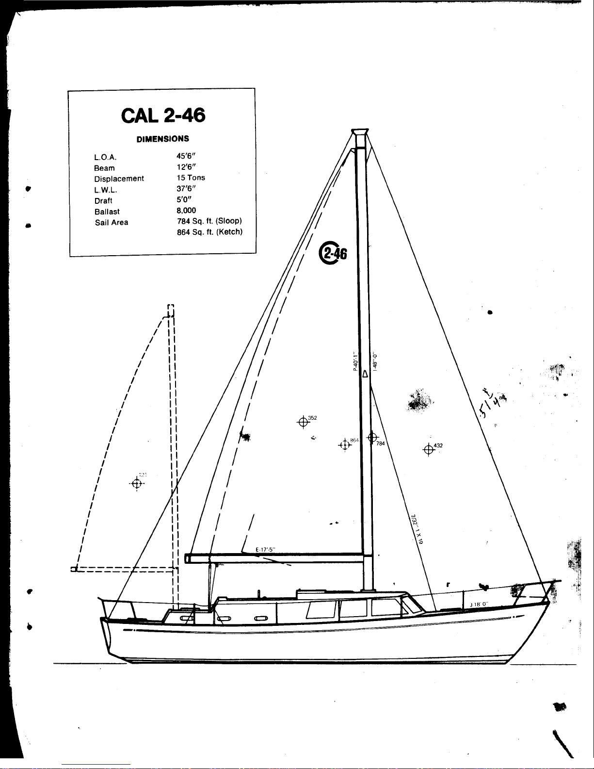
GAL/CRUISING
2-46
The
Master
Power
Control Panel
features
integrated,
simplified
controls
and
circuit
breaker
protection
to
permit
safe
and
efficient
operation
of
your
boat's
electrical
equipment.
All
panel components have been
carefully
selected
for
their
proven performance
in
marine
applications.
The
baSic
panel
is
of
a metal
alloy
which
is
inherently
corrosion
resistant
and
is
doubly
protected
to
optimize
resistance
to
the
effects
of
the
marine
envir-
onment. A
one
year
warranty
will
be
validated
by Marinetics Corporation,
P.O.
Box
1015, Newport Beach,
Calif.
92663,
if
the enclosed warranty
re-
gistration
form
is
submitted
within
30
days from the date of commissioning•
~/I.
()
It
1'1(-
~1Z
1JArV1:.5
Electrical
current
is
directed
from
two
12
volt,
~
batter~ythrough
the Master
Power
Control Panel
for
engine
starting,
battery
charging, and
accessory
loads.
Since the
GAL/CRUISING
2-46
is
designed
to
do
considerable
cruising
and
"living
aboard" an
optional
208
amp
battery
may
be added
to
meet
these
additional
electrical
requirements. Panel
selection
of
"BAT
1" or
"BAT
2"
determines which of the
two
battery
sets
will
be
utilized
for
engine
starting
and subsequent charging. Before
activating
the
electrical
system,
use the
Battery
Condition
Indicator
to
ascertain
the condition of your
batteries.
A.
BATl'ERY
CONDITION
INDICATOR
This type of
"indicator"
or
"meter"
is
technically
referred
to
as
a
"Suppressed Zero Voltmeter".
Note
that
calibrations
do
not
start
at
zero
but
provide a
full
scale
reading from 8
to
10
or
16
volts,
depending
on
the
meter.
Below
8
to
10
volts
the
battery
charge
is
so
low
that
terminal
voltage readings
are
meaningless. Approximate voltage range
interpretations
are
as
follows:
Engine
Not
Running
or
at
Idle
Engine
Running
Above
Idle
)
)
)
Below
II
- - - - - - Very
low
battery
charge
11 -12 ------
Low
battery
charge
12
-13 - - - - - - Well charged
battery
------------------ - ------
)
)
)
13
to
13* -----
Low
charge
rate
131
to
l5t
- - - - -
Alternator
&Voltage Regulator
OK
15i
or above - - - - Voltage Regulator out of Adjustment
It
is
iaportant
for
you
to
understand
that
the reading
on
the
Battery
Condition
Indicator
Dial
is
indexed from the
TOGGLE
TEST
SWITCH
POSITION
REGlRDLISS
OF
THE
MASTER
SWITCH
POSITION
unless
it
is
in
the
"BOTH"
position
•
When
the Master Switch
is
in
the
"BOTH"
position
then the
Battery
Condition
Indicator
Dial
wUl
indicate
BOTH
BATTERY
CONDITIONS
NO
MATTER
WHICH
WAY
THE
TOGGLE
TEST
SWITCH
IS
INDEXED.
When
the
Master Switch
is
in
either
the
"OFF",
"BAT
1"
or
"BAT
2" pOSitions, the
_ter
will
read the
condition
of
the
battery
TCJWA.RnS
which you index the Toggle
Test
Switch.
Note
that
panel
and meter
illumination
is
also
provided
bY'
this
same
Toggle
Test
Switch.
Before
activating
the
electrical
,sY'stem,
check the
condition
of
both
battery
sets
and then
select
the
STROl«lEST
BATTERY
FOR
ENGINE
STARTING.
-3-