ISE SY-8826 Manuel utilisateur

PRODUCT MAY VARY SLIGHTLY FROM THE ITEM PICTURED DUE TO MODEL UPGRADES.
PLEASE READ THIS INSTRUCTION VERY CAREFULLY BEFORE USING THIS
ITEM. YOU WILL FIND IMPORTANT INFORMATION REGARDING SAFETY OF
YOUR MAGNETIC BIKE.
+33 344 762 166
WWW.ISEFIT.COM
+49 681 98845400
WWW.ISEFIT.DE
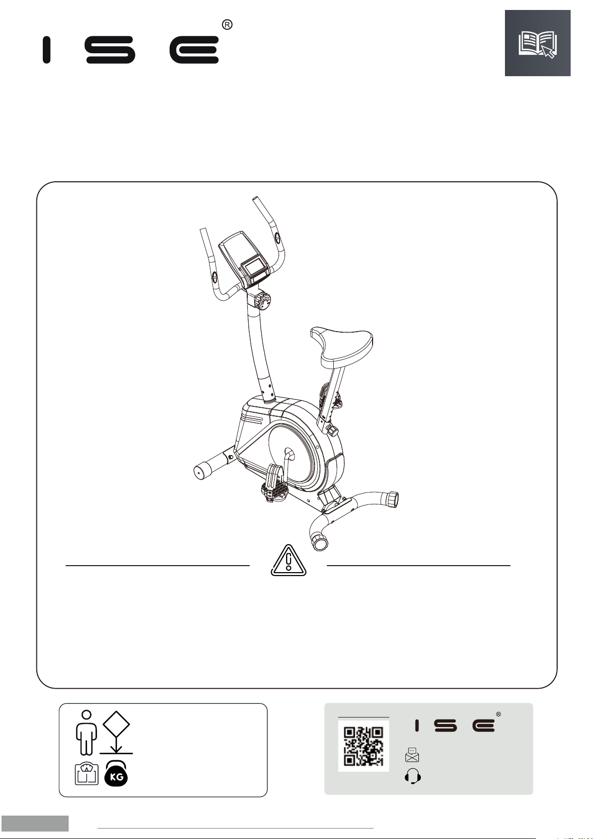
INSTRUCTION MANUAL
EXERCISE BIKE
SY-8826 (517B)
(ENGLISH)
1.
ENGLISH
100 KG
MAX USER
WEIGHT
+33 344 762 166
WWW.ISEFIT.COM

CONTENTS
This device concerned has been manufactured under an EU
Declaration of Conformity and compliance with all relevant EU
Directives, including CE(EN55014-1,EN55014-2);
EN957( EN ISO 20957-1, EN ISO 20957-5)
Please be assured that the box of this product is recycling, the rest of the packaging can be trashed.
In case the product contains batteries, do not trash directly.
DISTRIBUTED BY:
ISE GMBH
THEODOR-HEUSS-STRASSE 7
66130 SAARBRÜCKEN GÜDINGEN.
DEU - DEUTSCHLAND
TEL: +490681 98845400
WWW.ISEFIT.DE
IMPORTER:
SAS ISE
1 CHEMIN D’ARMANCOURT
60200 COMPIÈGNE. FRANCE
TEL: +33 344 762 1 66
PORT.: +33 6 32 91 85 26
CONTACT@ISEFIT.COM
WWW.ISEFIT.COM
WARNING:
A CORRECT LUBRICATION OF THE PRODUCT WITH SILICON OIL OR TEFLON IS REALLY IMPORTANT. THIS LUBRICATION
MUST BE PERFORMED REGULARLY DEPENDING ON EACH PERSON, EVEN BEFORE ITS FIRST USE.
YOU MUST PRESERVE THE ORIGINAL PACKAGING WITH ITS PROTECTIONS, PURCHASE RECEIPT, MANUAL AND
COMPONENTS DURING THE GUARANTEE PERIOD.
CHECK IN THE MANUAL THE MAXIMUM WEIGHT YOUR EQUIPMENT CAN SUPPORT. AN EXCESSIVE WEIGHT COULD
LEAD TO A MALFUNCTION IN THE OPERATING SYSTEM, WHICH WON’T BE COVERED BY THE GUARANTEE.
IMPORTANT SAFETY INSTRUCTIONS
PARTS LIST AND EXPLODED DIAGRAM
INSTALLATION GUIDE
EXERCISE INSTRUCTIONS
RESISTANCE LEVELS
HEART RATE
LEVELLING
CLEANING AND MAINTENANCE
MOVING THE BIKE
CUSTOMER CARE
DISPLAY INSTRUCTIONS
1.
2.
3.
4.
5.
6.
7.
8.
9.
10.
11.
3.
4.
6.
14.
15.
15.
15.
16.
16.
16.
17.
2.
ENGLISH
PRODUCT PARAMETERS
MODEL: SY-8826 (517B)
PRODUCT SIZE: 860*520*1200MM
RESISTANCE SYSTEM: MAGNETIC
ADJUSTABLE RESISTANCE: 8 LEVELS
MATERIAL: Q235 STEEL, PLASTIC SIDES
MAX. USER WEIGHT: 100 KG
G.W/N.W: 20.5KG/18.5KG
MANUAL IN FR / EN / DE / ES / IT
TEST STANDARD(S): EN ISO 20957-1, EN ISO 20957-5,
CLASS: HC (HOME USE)
Importer:
SAS ISE
1 Chemin d’Armancourt
60200 Compiègne France
TEL : +33 3 44 76 21 66
PORT : +33 6 32 91 85 26
www.isefit.com

1. IMPORTANT SAFETY INSTRUCTIONS
NOTE THE FOLLOWING PRECAUTION BEFORE ASSEMBLING OR OPERATING THE MACHINE
1. Assemble the machine exactly as the descriptions in the instruction manual.
2. Check all the screws, nuts and other connections before using the machine for the first time and ensure that
the trainer is in the safe condition.
3. Set up the machine in a dry level place and leave it away from moisture and water.
4. Place a suitable base (e.g. rubber mat, wooden board etc.) beneath the machine in the area of assembly to
avoid dirt and etc..
5. Before beginning training, remove all objects within a radius of 2 meters from the machine.
6. Do not use aggressive cleaning articles to clean the machine, Only use the supplied tools or suitable tools of
your own to assemble the machine or repair any parts of machine. Remove drops of sweat from the machine
immediately after finishing training.
7. Your health can be affected by incorrect or excessive training. Consult a doctor before beginning a training
program. He can define the maximum setting (Pulse. Watts. Duration of training etc) to which you may train
yourself and can get precise information during training. This machine is not suitable for therapeutic purpose.
8. Only do training on the machine when it is in correct working way. Use only original spare parts for any
necessary repairs.
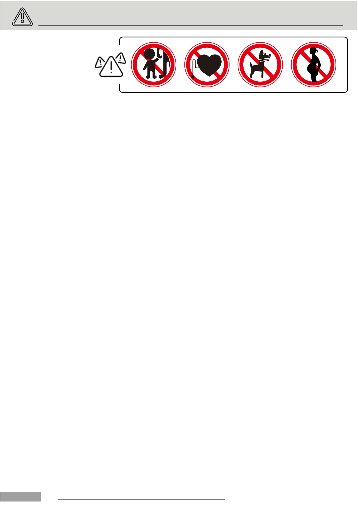
9. This machine can be used for only one person’s training at a time.
10. Wear training clothes and shoes, which are suitable for fitness training with the machine. Your training shoes
should be appropriate for the trainer.
11. If you have a feeling of dizziness, sickness or other abnormal symptoms, please stop training and consult a
doctor asp.
12. People such as children and handicapped persons should only use the machine in the presence of another
person who can give aid and advice.
13. The power of the machine increases with increasing the speed, and the reverse. The machine is equipped
with adjustable knob, which can adjust the resistance. Reduce the resistance by turning the adjusting knob
for the resistance setting towards stage 1. Increase the resistance by turning the adjusting knob for the
resistance setting towards stage 8. The maximum user’s weight is 100kg/220lbs.
14. Care must be taken when lifting or moving the equipment so as not to injure your back. Always use proper
lifting techniques and/or use assistance.
3.
ENGLISH

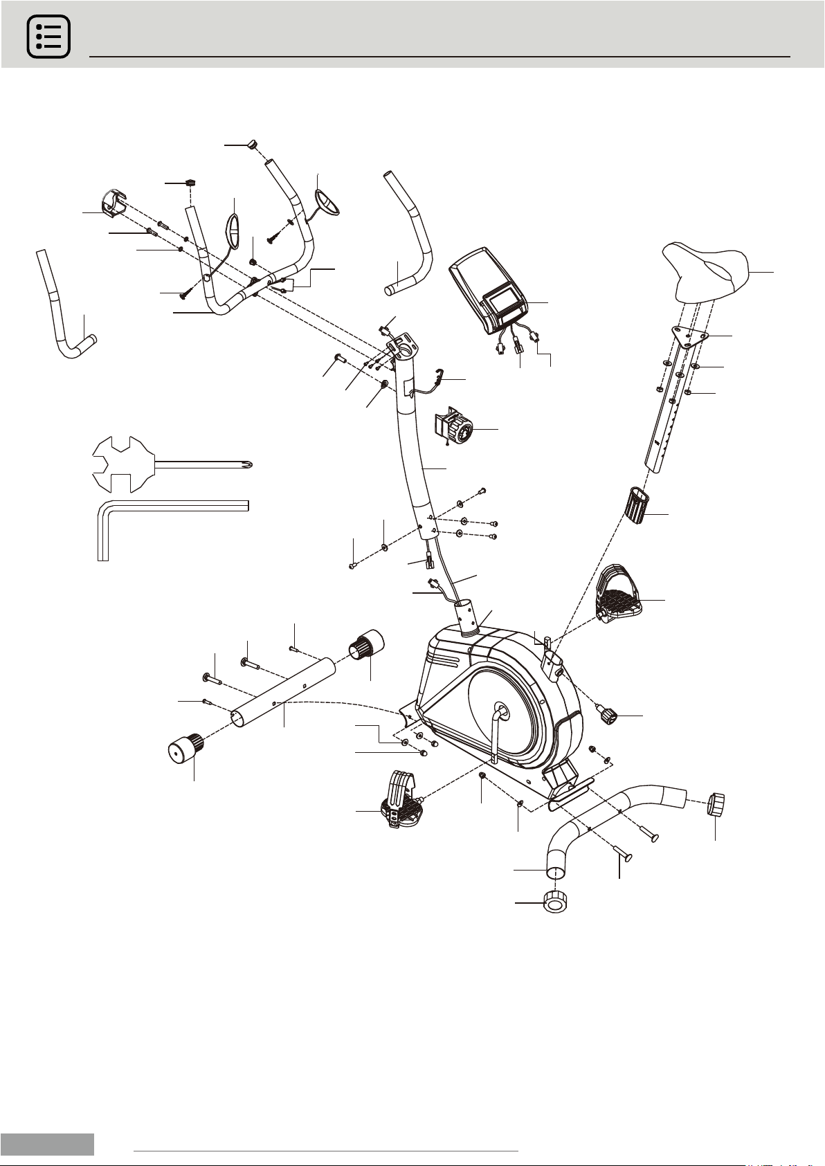
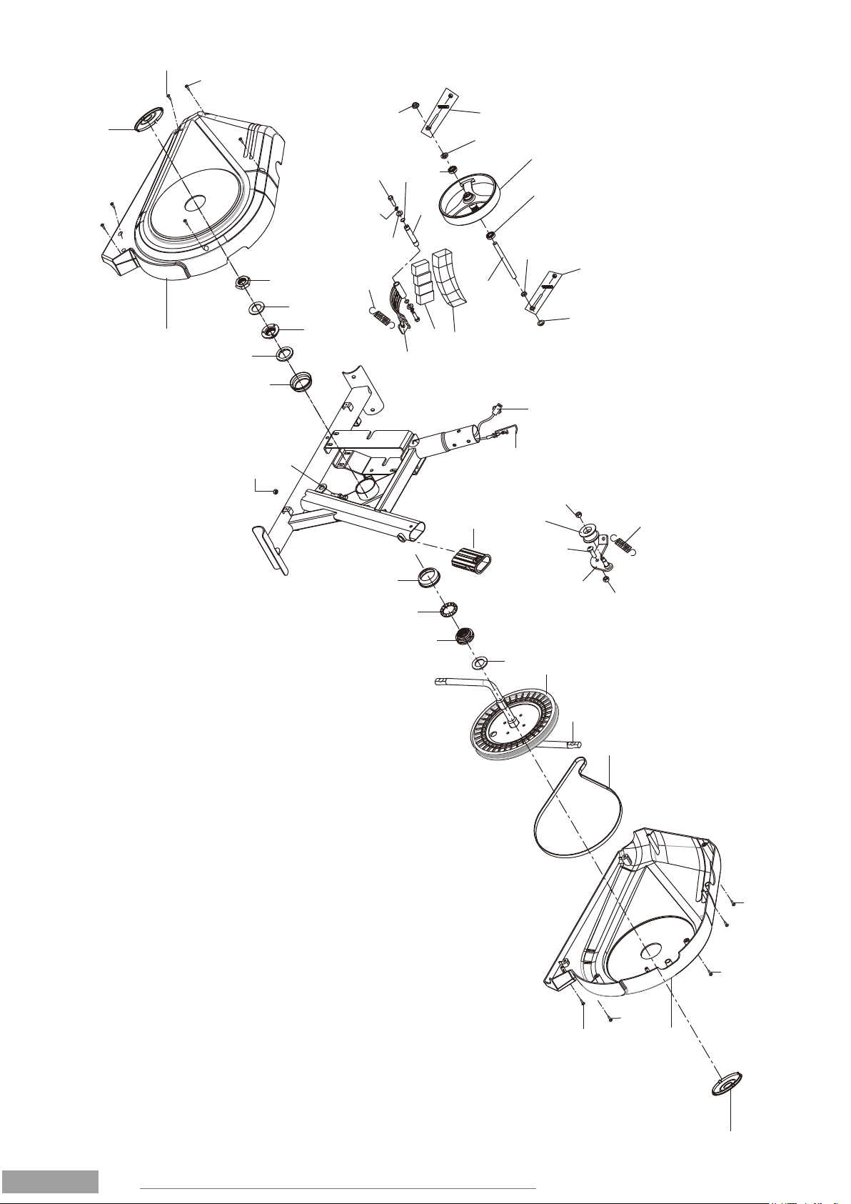
2. PARTS LIST AND EXPLODED DIAGRAM
4.
ENGLISH
24
23
24
16 16
17
25
17
25
27
27
26
16
28L
19
28R
30
36
11
35
34
31
29
20
22
21
17
18
15
21
14
13
64
7
75
10
39
32
6
4
74
3
2
1
1b 1a
3
5
20
37
38
42
42
12

5.
ENGLISH
22
21
49
48
50
51
52
19
53
45
46
47
48
49
29
41
42
41
57
60
62
57 64
61
58
58
59
63
70
69
66
65 67 68
72
73
71
56
55
43
43
42
40
54
9
40
33
8
43
43
44R
44L

3. INSTALLATION GUIDE
3.1 PREPARATION:
A. Before assembling make sure that you will have enough space
around the item.
B. Use the present tooling for assembling.
C. Before assembling please check whether all needed parts are
available (at the above of this instruction sheet you will find an
explosion drawing with all single parts (marked with numbers)
which this item consists of. ASSEMBLY REQUIRES
TWO PERSONS.
x2.
6.
ENGLISH
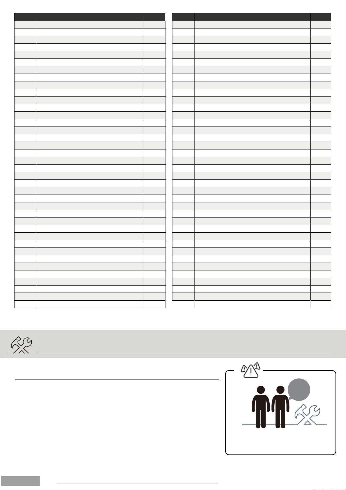
Nº NAME QTY. Nº NAME QTY.
1COMPUTER 1 39 SMALL COVER 1
2CROSSHEAD SCREW M5*10 2 40 NYLON NUT M8 2
3FOAM 241 CRANK END CAP 2
4HANDLE PULSE 242 SCREWS ST4.2X16 6
5HANDLEBAR 1 43 SCREWS ST4.2X19 7
6END CAP 2 44 CHAIN COVER (L/R) 2
7SCREWS ST4.2X19 245 NUT 1
8TENSION SPRING 146 WASHER 1
9BOLT M8X19 1 47 NUT II 1
10 BOLT M8X30 2 48 BALL BEARING 2
11 SEAT 149 COLLAR HOUSING 2
12 SUPPORT TUBE 150 NUT I 1
13 SCREWS M5 1 51 WASHER 1
14 ARC WASHER D6 1 52 RIBBED BELT PULLEY 1
15 TENSION KNOB 153 RIBBED BELT 1
16 CARRIAGE BOLT M8X60 454 IDLE WHEEL 1
17 ARC WASHER D8XØ20X1.5XR30 8 55 HEX BOLT M6 1
18 BOLT M8X16 4 56 HEX NUT M6 2
19 CRANK 157 U BRACKET 2
20 MIDDLE WIRE 158 BEARING 2
21 TENSION WIRE 1 59 AXLE 1
22 SENSOR WIRE 1 60 NUT 1
23 FRONT STABILIZER 161 NUT M10*1.0*5 1
24 END CAP Ø50 262 FLYWHEEL 1
25 DOMED NUT M8 4 63 NUT M10X1.0X2 1
26 REAR STABILIZER 1 64 NUT M10X1.0X5 1
27 REAR END CAP Ø60 265 BOLT M6X20 2
28 PEDAL (L/R) 266 JUMP RING D12 2
29 BUSHING 1 67 SPRING WASHER D6 2
30 TRIANGLE KNOB M16*1.5 1 68 WASHER D6 2
31 SEAT TUBE 169 AXLE 1
32 HANDLEBAR WIRE 270 MAGNET BOARD BRACKET 1
33 BELT BRACKET 1 71 TENSION SPRING 1
34 NYLON NUT M8 3 72 PLASTIC LATTICE 1
35 WASHER D8*Ø16X1.5 373 MAGNET 4
36 MAIN FRAME 174 WASHER D8 2
37 OPEN-END WRENCH S13-14-15 1 75 END CAP 2
38
SOCK HEAD WRENCH S6
1

3.2 ASSEMBLY INSTRUCTION:
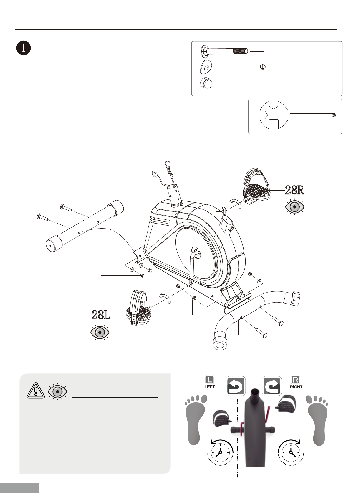
Attach the front stabilizer (23) and the rear stabilizer (26)
to the main frame (36) with carriage bolt (16)& domed nut
(25) and arc washer (7).
Attach the pedal(28L/R) to the crank arms as shown in
FIG.1.
CAUTION: be sure the right pedal (28R) marked (R) is
attached to the right crank arm and tightened in the
clockwise direction.
The left pedal (28L) marked (L) is attached to the left crank
arm and tightened in the anticlockwise direction.
FIGURE 1.
7.
ENGLISH
LEFT PEDAL RIGHT PEDAL
LEFT PEDAL: The left pedal is marked on its
axis with the letter L (left).
Screw the shaft in the counterclockwise
direction.
RIGHT PEDAL: The right pedal is marked on
its axis with the letter R (right).
Screw the shaft in a clockwise direction.
ATTENTION:
#16 M8*60 4PCS
#17 d8* 20*1.5*R30 4PCS
#25 M8 4PCS
S15
S13
16
23 17
25
25
17
16
26
28L
19 28R

FIGURE 2.
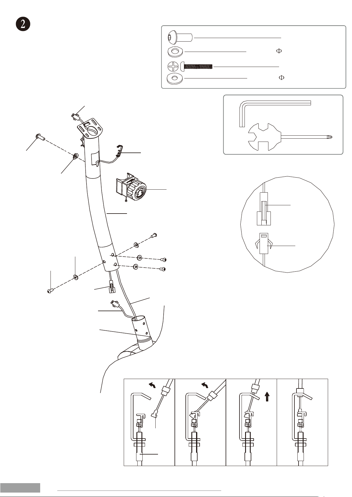
First, connect the sensor wire(20)&(22)and
tension control wire (21&15) with bolt (13),
arc washer (14) as shown in FIG.2, and install
the support tube (12) on the main frame (36)
with bolt (18), arc washer (17) .
8.
ENGLISH
#13 M5*45 1PC
#14 d6* 12*1.5*R30 1PC
#18 M8*16 4PCS
#17 d8* 20*1.5*R30 4PCS
36
20
22
21
17
18
15
21
14
20
13
12
20
22
15
21

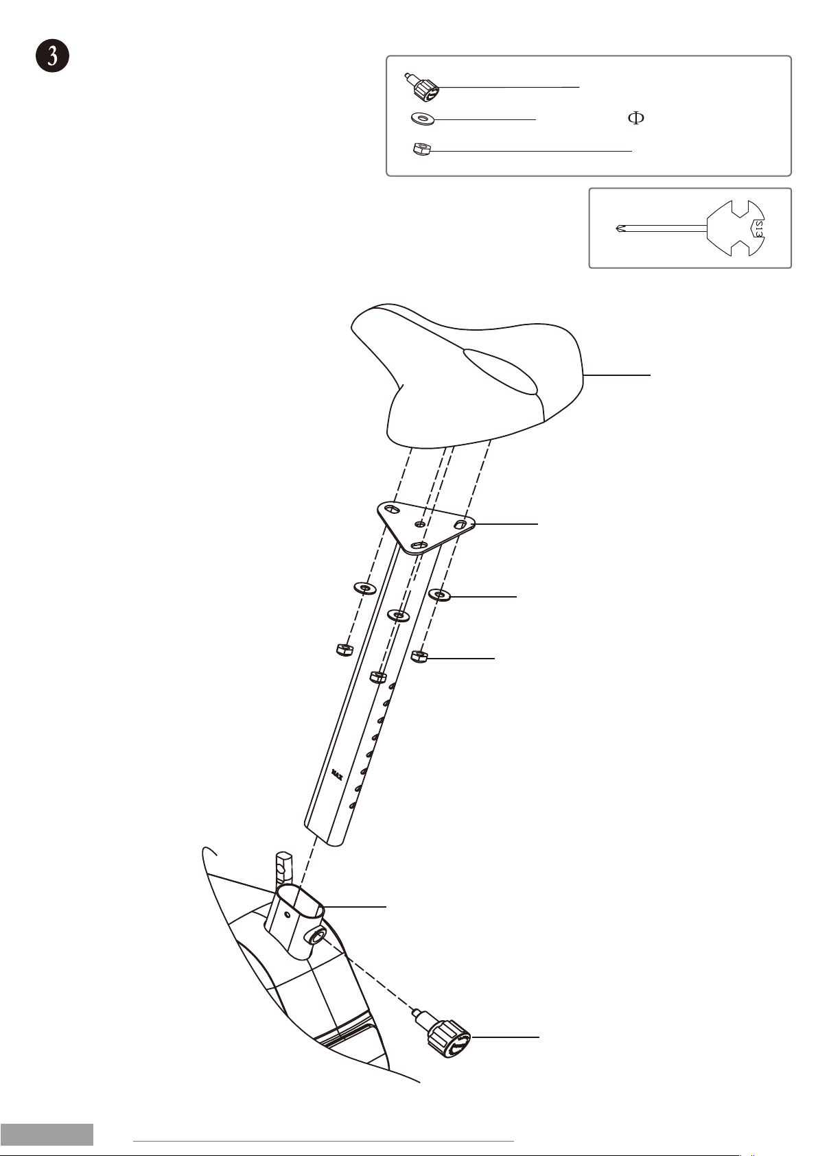
FIGURE 3.
9.
ENGLISH
30
11
35
34
31
36
#30 M16*1.5 1PC
#35 d8* 20*1.5 3PCS
#34 M8 3PCS
Attach the seat (11) to the vertical seat post
(31) with the nut (34) and washer (35).
Insert the vertical Seat Post (31) into the main
frame (36) and line up the holes. Secure the
seat in position with the Adjustment Knob (30).
The correct height for the seat can be adjusted
after the bike is fully assembled.

FIGURE 4.
10.
ENGLISH
1
1b 1a
1b
20
1a
32
75
10
39
32
74
2
5
20
12
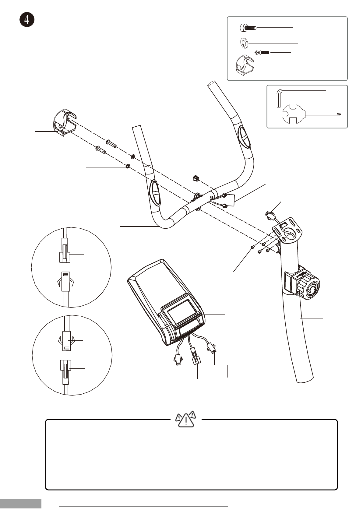
#10 M8*30 2PCS
#74 d8 2PCS
#39 1PC
#2 M5*10 4PCS
Attach the handlebar (5) to the support tube (12) with washer
(74)and Bolt(10. Connect computer wire 1b with sensor wire
(20). Connect computer wire 1a with handle pulse wire (32).
Attach computer (1) onto support tube (12) with bolt (2).
Then attach small cover (39) to handlebar (5). FIG.4
CAUTION: MAKE SURE YOU HAVE TIGHTENED ALL THE BOLTS AND NUTS WELL
BEFORE BEGINNING YOUR WORKOUT.
NOTE: THE END CAP ON THE FRONT STABILIZER TUBE IS MOVABLE, WHICH IT
IS EASY FOR YOU TO MOVE YOUR TRAINING BIKE, AND THE END CAP ON THE
REAR STABILIZER CAN ADJUST THE PARALLELISM.
Ce manuel convient aux modèles suivants
1
Table des matières
Langues :
Autres manuels ISE vélo d'appartement
Manuels vélo d'appartement populaires d'autres marques

Stamina
Stamina 1310 Manuel utilisateur

American Fitness
American Fitness SPR-BK1072A Manuel utilisateur

Cateye
Cateye CS-1000 (CYCLO SIMULATOR) Manuel utilisateur

BH FITNESS
BH FITNESS H9158H Manuel de l'opérateur

Body Sculpture
Body Sculpture BC-7220G Manuel utilisateur

Cateye
Cateye EC-2300 Manuel utilisateur