Iridium ICHU1000 Manuel utilisateur

IRIDIUM ICHU1000
Installation Manual
Single Channel Unit
Iridium Satellite LLC
8440 South River Parkway
Tempe,AZ 85284 USA
Tel. Toll Free
1-866-947-4348
Local or International
1-480-752-5155
E-mail [email protected]

Introduction
Congratulations on your new Iridium handset or PSTN (Public
Switched Telephone Network) telephone.
Your Iridium system is a modular system that consists of an antenna,
transmitter/receiver, handset and/or desk unit, and optional PSTN
telephone/PBX (Private Branch Exchange) switchboard.
You can operate the Iridium system in voice mode from a handset,
desk unit, and/or PSTN telephone. To the system you can connect
up to five handsets or desk units and one PSTN telephone or PBX
switchboard.
Please note
Any responsibility or liability for loss or damage in connection with
the use of this product and the accompanying documentation is
disclaimed. The information in this manual is furnished for informa-
tional use only, is subject to change without notice, may contain
errors or inaccuracies, and represents no commitment whatsoever.
This agreement is governed by the laws of Denmark.
Doc. no.: M4150GB1 Issue:A/0125

1
Installation
IRIDIUM
0125
Contents
1 Configuration of Single-Channel Unit.............................................................................................................. 2
2 Installation .......................................................................................................................................................... 2
2.1 Cable Overview .................................................................................................................................................... 2
2.2 Where to Place the Satellite Transceiver Box ..................................................................................................... 4
2.3 How to Mount the Satellite Transceiver Box........................................................................................................ 5
2.4 How to Put on the Finishing Cover ...................................................................................................................... 6
2.5 How to Insert the SIM Card.................................................................................................................................. 7
2.6 How to Remove the Finishing Cover ................................................................................................................... 8
2.7 How to Change the Antenna Cable Position ....................................................................................................... 9
2.8 Installation of the Antenna.................................................................................................................................... 11
2.9 PABX/PSTN Interface .......................................................................................................................................... 13
2.10 Data Interface....................................................................................................................................................... 13
Appendix A ..................................................................................................................................................................... 17
Spareparts List ..................................................................................................................................................... 17

2
Installation IRIDIUM
0125
1 Configuration of Single-Channel Unit
L1
35423D
10 - 32V DC
PABX
Phone
DTE
2
3
4
1
Antenna Unit
Max. cable loss 3dB
Iridium
L1 + L2 < 100 metres
L2
Box
Connection
5
1
Handset
Control
Handset
Transceiver
Unit
Control
2 Installation
2.1 Cable Overview
Cable 1
Scanbus
Cable: 9*0.22 mm2shielded
shield connected to ground
Cable connector type: 9 pole sub-d male

3
Installation
IRIDIUM
Transceiver Description Handset Colour
1NC1
2 data+ 2 white Twisted
3 data- 3 brown pairs
4AF+4greenTwisted
5 AF- 5 yellow pairs
6 GND 6 grey Twisted
7+24VDC7 pinkpairs
8 RX_AF+ 8 blue Twisted
9RX_AF-9 redpairs
shield GND shield
2
3
4
5
6
7
8
9
1
10
36088
Cable 2
Phone
Cable connector type: RJ 11
Transceiver Description Veritas
1NC1
2 phone1+ 2
3 phone1- 3
4NC4
Cable 3
Data
Cable: 9*0.22 mm2shielded
shield connected to ground
Cable connector type: 9 pole sub-d male
Transceiver Description Veritas
1 DCD 1
2 received data 2
3 transmitted data 3
4 data terminal ready 4
5 serial GND 5
6 data set ready 6
7 request to send 7
8 clear to send 8
9RI9
shield GND shield
0125

4
Installation IRIDIUM
0125
Cable 4
Power supply Front view
Pin no. Description Colour
1 10-32V DC red
2 0V DC black
3NC white
4 GND green
4
3
1
2
36662A
Cable 5
Description of connections to T-connection H4196
The wire terminal blocks are connected in parallel.
36090
2.2 Where to Place the Satellite Transceiver Box
Mount the satellite transceiver box in a place where it is sheltered from the wind, protected from the salty and humid
sea atmosphere. The temperature must not exceed 55° C.
To ensure that the SIM card is easily accessible, do not place the satellite transceiver box higher than 1.5 m above
the floor.
5
Installation
IRIDIUM
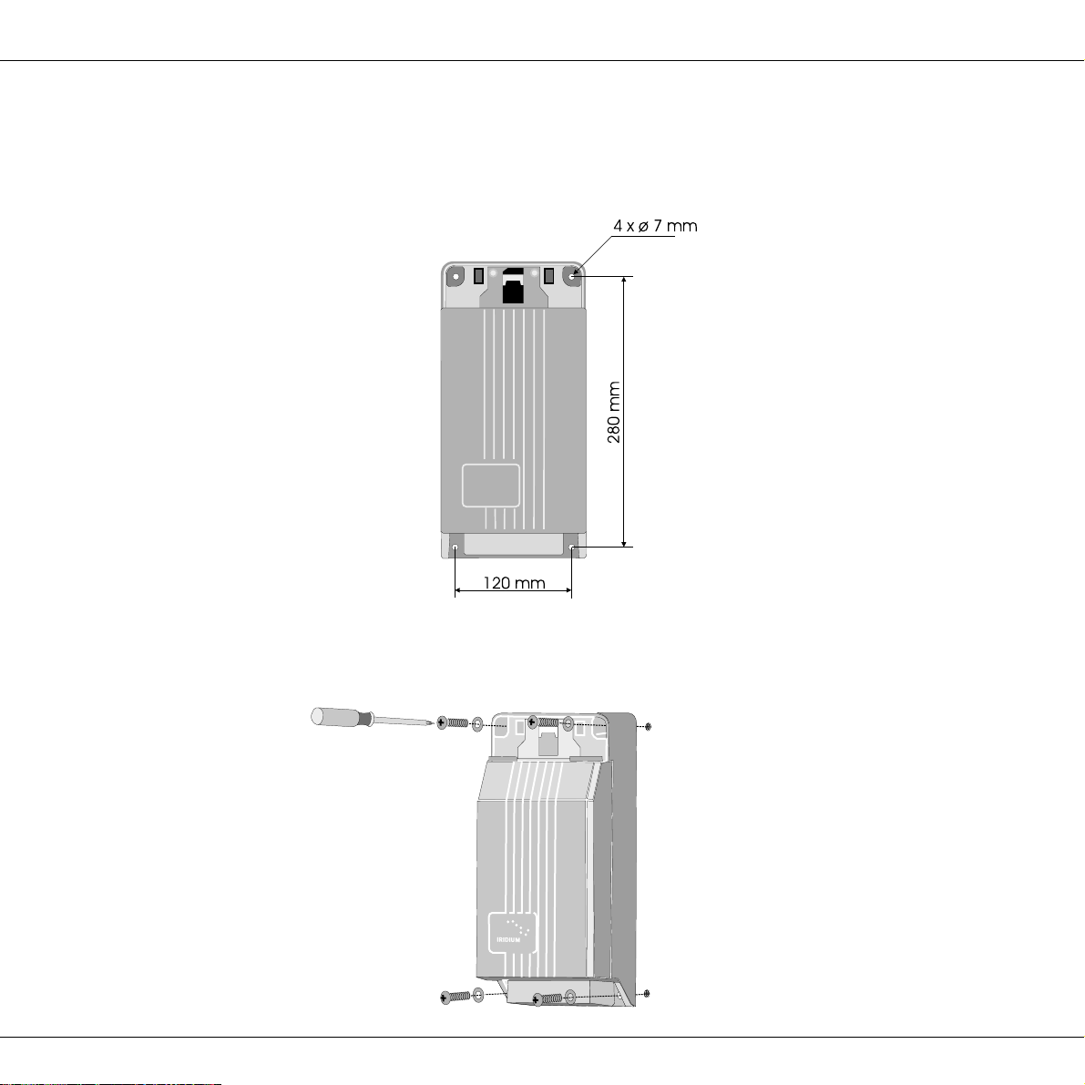
2.3 How to Mount the Satellite Transceiver Box
Fix the satellite transceiver box to the wall using the four screws included in the package. The screws are positioned
as shown below:
First tighten three of the screws. The wall surface should be plane. If there is a discrepancy in planeness exceeding
1 mm, level the discrepancy up by shims or washers under the fourth screw before this is tightened.
0125

6
Installation IRIDIUM
Inside of finishing cover:
2.4 How to Put on the Finishing Cover
When the satellite transceiver box has been mounted on the wall, put on the finishing cover.
Thesmalllidinthefinishingcovershouldbeshut.Pressthehooksinsidethefinishingcoverdownonthetwothinedges
ofthe satellite transceiver box.While pressing, let thetwo plastic spears insidethe finishing cover intothe two square
holes of the satellite transceiver box.
Press hard on the spots shown in the picture below until a loud click is heard.
When putting on the finishing cover, do not use any tools – only your hands.
0125

7
Installation
IRIDIUM
0125
2.5 How to Insert the SIM Card
First, open the small lid in the finishing cover protecting
the SIM card reader. Then go through each of the follow-
ing steps:
Unlock the SIM card holder by pushing the lock with your
finger nail.
Lift the SIM card holder so that the slot points upwards.
Insert the SIM card in the slot. Make sure that the cut-off
corner of the card is placed as shown in the picture.
Push the SIM card holder back down, and lock it by
pushing the lock with a finger nail.
Finally, shut the lid again.
8
Installation IRIDIUM
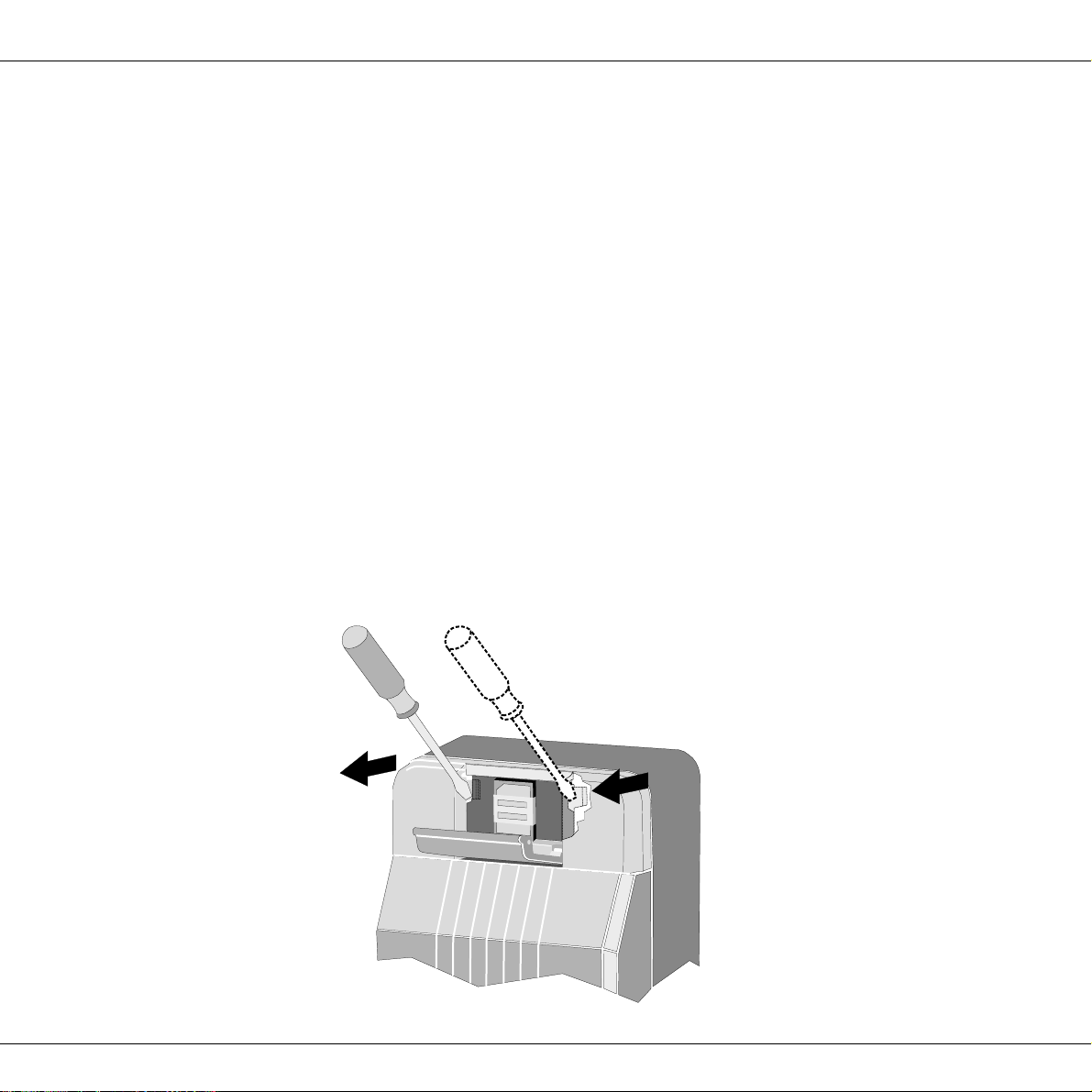
2.6 How to Remove the Finishing Cover
You may need to dismount the satellite transceiver box from the wall, e.g. in connection with service.
For access to the mounting screws, the finishing cover can be removed from the satellite transceiver box as follows:
Put a screwdriver into the slot in the printed circuit board beside the SIM card reader, and press gently
to unhook the plastic spear.
While pressing with the screwdriver, lift up the same side of the finishing cover slightly to loosen it.
Repeat this procedure on the other side of the finishing cover.
You can now detach the finishing cover from the satellite transceiver box by pulling it gently upwards.
0125
Autres manuels pour ICHU1000
1
Table des matières
Autres manuels Iridium Combiné


