InVid Tech ICON-Pro Manuel utilisateur

ICON- Pro
MANUAL
November 2023
Fw. v. 1.135
M v. 1.15

2ICON-Pro
CONTENTS
Introduction
Default Device Settings
Device Specifications
Device Dimensions
Device Connection Terminals
Installation Recommendations
Wiegand Reader (Connection Diagram)
Open Supervised Device Protocol Reader (Connection Diagram) Coming soon!
Exit Button & Door Position Sensor (Connection Diagram)
Electric Lock [Power Supply +12 VDC] (Connection Diagram)
Electric Lock [Power Over Ethernet] (Connection Diagram)
Third-Party Device [Relay +12 VDC] (Connection Diagram)
Connecting to Device
Login
Quick Start
System
Network
Open Supervised Device Protocol (OSDP) OSDP is coming soon!
Maintenance
Hardware reset with the button
Glossary
For Notes
3
3
4
5
6
7
9
11
13
14
15
16
17
17
18
19
20
22
23
24
25
28

Introduction
Default Device Settings
This document provides detailed information on the ICON-Pro
Controller device structure and steps for installing and connecting it.
It also includes instructions for preventing or troubleshooting many
common problems.
This guide is for informational purposes only, and in the event of any
discrepancies, the actual product takes precedence.
All instructions, software, and functionality are subject to change
without prior notice.
The latest version of the manual and additional documentation can
be found on our website or by contacting customer support.
The user or installer is responsible for complying with local laws and
privacy regulations when collecting personal data during the use of
the product.
ICON_(serial number)
192.168.4.1
192.168.1.100
None
admin
admin
30 minutes
3ICON-Pro
•Wi-Fi device name when searching
• Device access point (AP) Wi-Fi Internet protocol
(IP) address
• Default Ethernet IP address of the device
•Wi-Fi password
•Login
•Password
•AP Wi-Fi timer

Communications
•Wi-Fi
• Ethernet
• Wiegand Readers ports
•Open Supervised Device Protocol (OSDP) via RS-485 port
• USB ports (Type-C)
802.11 b/g/n 2.4 GHz
RJ-45 (10/100 Mbit)
2
1
Yes
12-24 VDC +/- 10 %
PoE /802.3af: 2 A (24 W) IEEE802.3
0.5 A (6 W)
0.21 A (2.52 W)
1.5 A (45 W)
Yes
Yes
Electrical characteristics
• Input voltage
• Operation current (MAX) 12 VDC
• Operation current (AVG) 12 VDC
•Relay contact rating 30 VDC
•Output short-circuit protection
•Power supply reverse polarity protection
ICON-Pro
ESP32-S3
Yes
Yes
Yes
100 000
250 000
8
4 Relay
1
Built-in
Physical connections
• Inputs
• Outputs
• Emergency In
• Tamper G-sensor
Device Specifications
Environmental requirements
•Operating temperature
•Ingress Protection rating
-22°F ~ 158°F (-30°C ~ 70°C)
IP50
Physical characteristics
•Housing material
•Mounting method
•Dimensions (length, width, height)
•Weight
ABS plastic UL94 V-0
Wall mount/Din rail mount (option)
5.9" x 3.15" x 1.38" (150 x 80 x 35 mm)
6.75 oz (191 g)
* See general specifications for RS4-85 interface.
Device info
• Model
• Processor
• Over-the air (OTA) update
• Built-in web server
•Message Queuing Telemetry Transport (MQTT)
application programming interface (API) provided
•Users
• Events
3280 ft (1000 m)
328 ft (100 m)
33 ft (10 m)
328 ft (100 m)
Work distance
• RS-485*
• Wiegand
• Wi-Fi 2.4 GHz (open space)
• Ethernet RJ-45 (10/100 Mbit)
4ICON-Pro
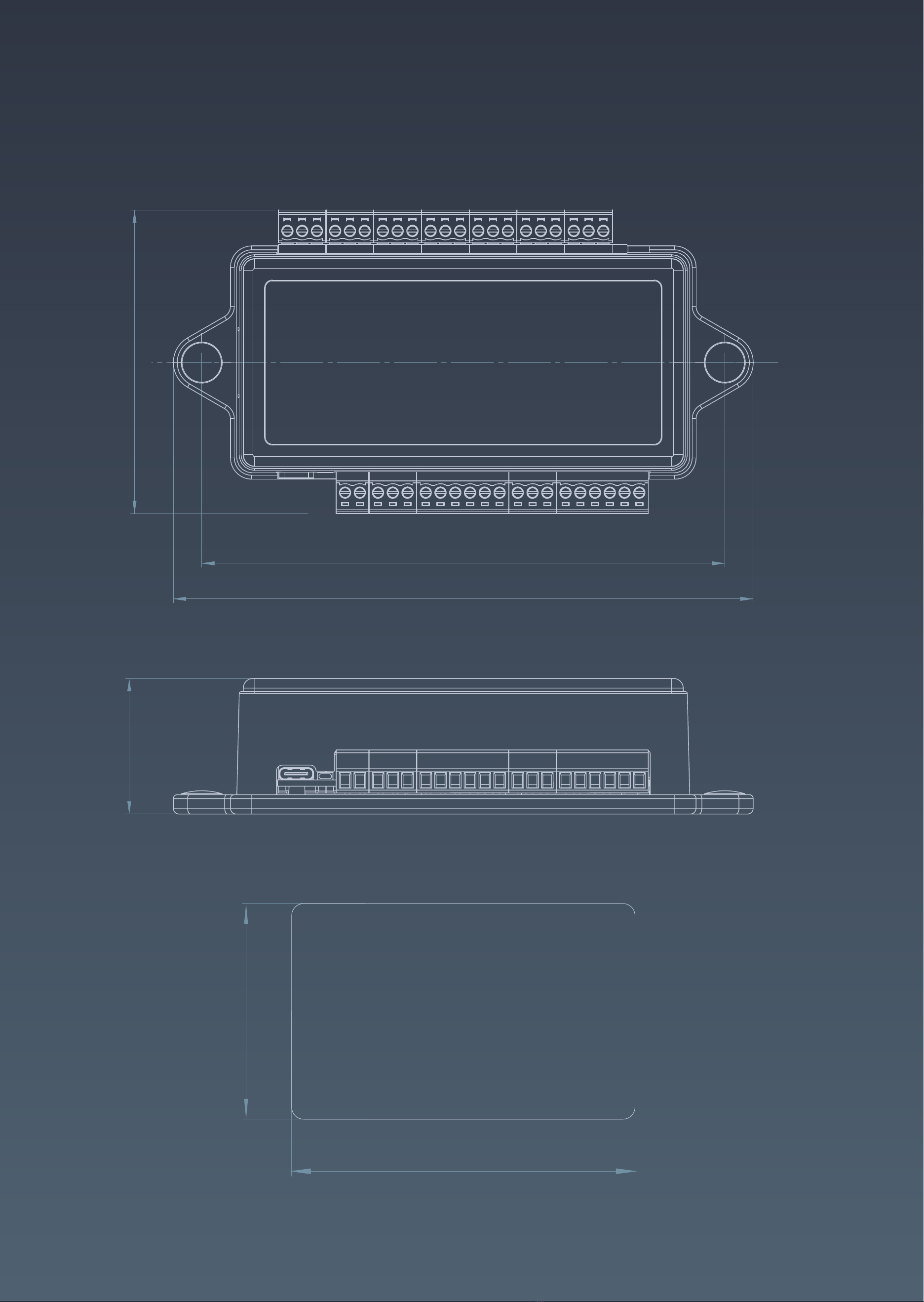
Device Dimensions
5ICON-Pro
5.31"
5.9"
3.15"
1.38"
2.125"
3.375"
125, 65535
RFID CARD

ICON-Pro device connection terminalsDevice Connection Terminals
The manufacturer reserves the right to modify the external pin assignments and their placement, as well as the appearance of the device
without prior notice.
These changes may be made to improve functionality or ergonomics, or to comply with technical requirements and standards.
Users are advised to consult the latest versions of technical documentation and instructions before using the device.
LED Indication
Power IN
GND
+VDC
Door 2 IN
Door Position Sensor
GND
Request to Exit
Red-
Yellow-
Blue-
Wiegand 2 IN
+VDC
GND
Buzzer
LED
D 1
D 0
RJ-45 Ethernet Port
Local Area Network
Door 1 IN
Door Position Sensor
GND
Request to Exit
Wiegand 1 IN
+VDC
GND
Buzzer
LED
D 1
D 0
EXT 1
Emergency IN
RS-485 B-
RS-485 A+
Relay 1
NC
C
NO
Door 3 IN
Request to Exit
GND
Door Position Sensor
Door 4 IN
Request to Exit
GND
Door Position Sensor
Relay 2
NC
C
NO
Relay 3
NC
C
NO
Relay 4
NC
C
NO
Service Button
Reset
USB Service Port
Type-C
6ICON-Pro

Installation Recommendations
7ICON-Pro
Placement and Wiring
Place controllers as close as possible to Wi-Fi APs to minimize latency.
Check the Wi-Fi signal strength after installation, and make sure the
minimum allowable signal level is -75 dB. If the signal strength is lower,
move the AP closer to the device, or use a stronger antenna on the AP or
device. Avoid placing the device on metal surfaces, as this may reduce the
quality of the Wi-Fi connections.
Connecting Power to the Device
Make all connections only when the power is off.
Use a power cable with a suitable cross-section to supply the current
consumption of the connected devices. Make sure to use two separate
power supplies for the controller and the actuators.
Wiegand Connection
Use the same Wiegand format and byte order to connect the readers to
avoid differences in card code reading and subsequent confusion in the
system.
The Wiegand communication line length should not exceed 328 ft (100 m).
If the communication line is longer than 16.4 ft (5 m), use a UTP Cat 5E
cable. The line should be less than 1.64 ft (0.5 m) away from power cables.
Keep the reader power line wires as short as possible to avoid a
significant voltage drop across them. After laying the cables, make
sure that the power supply voltage to the reader is at least 12 V
when the locks are on.
Connecting OSDP
The OSDP uses an RS-485 interface that is designed for long-distance
communications. It operates at ranges up to 3,280 ft (1,000 m) with good
resistance to noise interference.
The OSDP communication line should be laid as far away as possible from
power cables and electric lights. A one-twisted pair, shielded cable, 120Ω
impedance, 24 AWG should be used as the OSDP communication line (if
possible, ground the shield at one end).

Installation Recommendations
8ICON-Pro
Connecting Electric Locks
Connect devices via relays if galvanic isolation from the device to be
controlled is needed, or if you need to control high-voltage devices or
devices with significant current consumption.
To ensure reliable system operations, it is best to use one power source for
the controllers and a separate one for the actuators.
Protection against high current surges.
A protective diode is used to protect the controller from reverse currents
when an electromagnetic or electromechanical lock is triggered. A
protective diode or varistor is installed near the lock in parallel with the
contacts. THE DIODE IS CONNECTED IN REVERSE POLARITY.
Suitable diodes include SR5100, SF18, SF56, HER307, and similar. Instead of
diodes, varistors 5D330K, 7D330K, 10D470K, and 10D390K can be used, for
which there is no need to observe polarity.

Wiegand Reader
Connection Diagram
1 2
34
56
7 8
9 0
*#
Red
Black
Brown+Yellow
Orange
White
Green
+VDC
GND
LED Red+Beeper
LED Green
Data 1
Data 0
1 2
34
56
7 8
9 0
*#
9ICON-Pro
HID Signo Keypad Reader 20K
The wiring diagram is shown as an example.
In reality, wire colors may vary depending on the model of the third-party reader.
Please refer to the reader manufacturer's instructions.
Before you start building cable networks for Wiegand readers, read the interface specifications.

Wiegand Reader
Connection Diagram
10ICON-Pro
Lumiring AIR-R Reader
Before you start building cable networks for Wiegand readers, read the interface specifications.
Red
Black
Brown
Orange
White
Green
+VDC
GND
LED Red
LED Green
Data 1
Data 0
Table des matières
Autres manuels InVid Tech Contrôleurs


