Intermatic HA09 Manuel utilisateur

Page 1 of 20 158HA11646
HA09 - HANDY REMOTE CONTROLLER INSTRUCTIONS
Thank you for purchasing Intermatic’s HomeSettings
devices. With these products you can reliably and remotely
control lighting and appliances. The outstanding features of
the HomeSettings program include:
Feedback that will allow you to see whether your
device has received the ON/OFF/DIM signal.
Ease of installation
RF signal reliability – each HomeSettings product
has a special repeater feature that virtually
guarantees that RF signals are received.
If required, more than one controller can be used
for the same system.

Page 2 of 20
Z-Wave™ Introduction
The HA09 Handy Remote Controller is a Z-Wave™ enabled device
and is fully compatible with any Home Settings network and any Z-
Wave™ enabled network. Z-Wave™ enabled devices displaying the
Z-Wave™ logo can also be used with Home Settings modules and
controllers regardless of the manufacturer, and Home Settings
modules and controllers can also be used in other manufacturer’s Z-
Wave™ enabled networks. Each module in a Home Settings network
is designed to act as a repeater. Repeaters can re-transmit the RF
signal to ensure that the signal is received by its intended destination
by routing the signal around obstacles and radio dead spots.
________________Table of Contents
Glossary of Terms………………………………………….……….. 3
Installing Batteries……………………………………………………5
Module Installation and Set-up Recommendations………………6
Creating a network………………………………………………….. 6
________________Table of Contents (continued)
INCLUDE Modules to a Network………………………………. 7
Associating Modules to Channels………………………………9
Exclude from Network…………………………………………. 11
Exclude from Channel…………………………………………. 11
Remote ON/OFF/DIM Operation…………………………………...12
Resetting the Controller…………………………………………….. 13
Resetting the CHANNELS only…………………..……………..13
Resetting the NETWORK and CHANNELS…..……….………13
Additional Features…………………………………………………..14
Controller Replication…………………………………...………. 14
Replicating the Network and Channel Settings……………... 14
Replicating the Network only………………………….…………….16
Troubleshooting……………………………………..………………. 17
Federal Communications Commission Statement………………. 19
Specification Information…………………………………………….19
Warranty Information…………………………………………….…..20

Page 3 of 20
Glossary of Terms
Channel – A channel will control up to 16 modules, allowing
them to be programmed to turn on/off with the same time
settings. HA09 has 6 channels.
Device – Any item that is connected to a module (for
example, lamps).
Module – Any Intermatic HomeSettings product that is
controlled with a remote controller. A module can be
controlled by more than one channel.
Network – A collection of devices controlled by primary and
secondary controllers operating on the same system.
Each network has its own unique identification code so
that no one else can control the system.
Primary Controller – The first controller used to set up your
modules and network. NOTE: Only the Primary Controller
can be used to include or delete modules from a network.
Scene – Lighting modules assigned to the various channels
can be set at different levels, thus creating desired light
levels throughout your house called scenes. Scenes can
be set during the “Associating Modules To a Channel”
step (page 9) by choosing ON, OFF and/or DIM settings.
Secondary Controller – A controller containing network
information about other modules within the network, and is
created the primary controller. Secondary controllers
cannot include or delete modules to the network.

Page 4 of 20
Handy 6-Channel Remote Controller _
Fig 1. HA09 Handy Remote Controller

Page 5 of 20
Installing Batteries
1. Open the battery compartment door located on the
back of the remote control by pressing down on
the battery compartment tab and pulling the door
outward. (See Fig 2a)
2. Insert 4 AAA alkaline batteries (not included),
placing the batteries as shown in the
compartment. (See Fig 2b)
3. Replace the battery compartment door by first
inserting the 2 tabs at the bottom of the door, then
pressing the door in until the door clicks shut.
Fig 2a. Battery compartment door Fig 2b. Battery compartment

Page 6 of 20
Installation and Set-Up Recommendations
1. Modules should be plugged into or hardwired into the
location where they will be used.
2. For best results, do not move or relocate modules after
they have been included into the network. If you wish to
re-locate or move a module from a particular location,
first delete it from the network, then include it back to
the network after you have re-located it.
3. Devices should be plugged into modules before adding
modules to the network. Devices (for example, lamps)
should be turned to the ON position.
4. Controllers must be brought within 6 ft. of modules
during set-up. This is because during set-up, the
controller communicates with the modules using low
radio transmission power. This helps provide additional
security when setting up your network.
5. HA06 Dimmer Switches have a 40-Watt minimum lamp
requirement.
Creating a Network
NOTE: Creating a network refers to assigning modules to
the master controller. All modules must be assigned to the
master controller before any programming or remote control
functions can be accomplished.
Page 7 of 20
____________INCLUDE Modules to a Network_________
NOTE: Devices should be plugged into modules before
adding modules to the network. Devices (for example,
lamps) should be turned to the ON position.
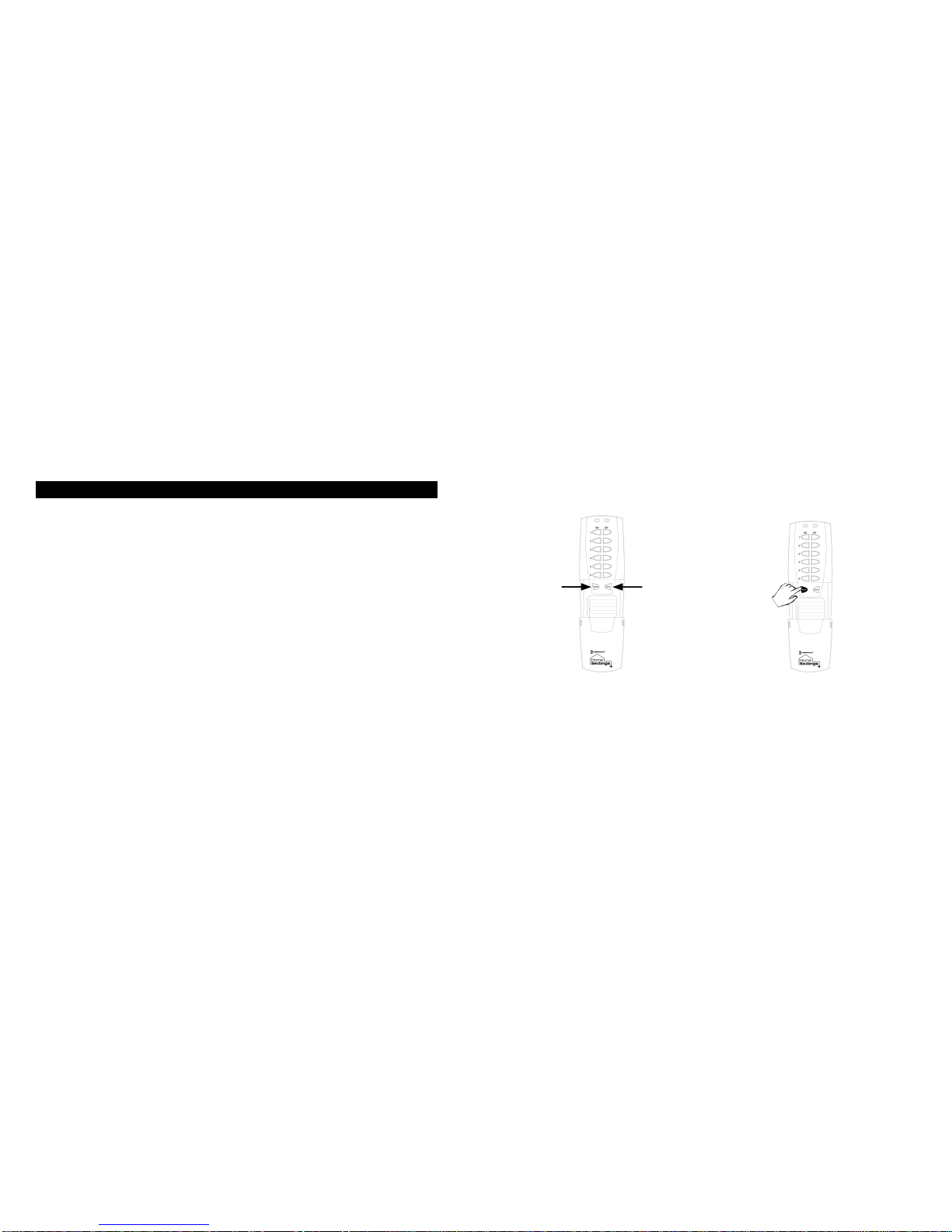
1. (See Fig 3a) While holding the door grips, slide the
cover down to reveal the INCLUDE and DELETE
buttons.
2. (See Fig 3b) Press and release the INCLUDE
button. The green LED will flash indicating that
the controller is ready to add modules to the
system. (If the green LED stops flashing, the
controller has “timed out”. The INCLUDE button
must be pressed again).
Fig 3a. Access the INCLUDE Fig 3b. Press and release
and DELETE buttons the INCLUDE button

Page 8 of 20
Creating a Network (continued)
3. (See Fig 3c) Press and release the programming
button on the module. If successful, the LED on
the controller and module will turn solid green. If
not successful, the red LED will flash and it will be
necessary to repeat steps 2 and 3 until the green
LED on the controller turns solid green and does
not flash.
4. Repeat steps 2 and 3 for each module you wish to
include into the network.
Fig 3c. Press and release the programming button

Page 9 of 20
Associating Modules to Channels
1. (See Fig 4a on page 10) On the remote controller,
simultaneously press and hold the ON and OFF
buttons of the desired channel. Both red and green
LED’s will flash. (Note: The LED’s will time out after 10
seconds. If this happens, ON and OFF buttons have to
be pressed again). Release the ON and OFF buttons.
2. (See Fig 4b on page 10) Press and hold the INCLUDE
button.
3. (See Fig 4c on page 10) While holding the INCLUDE
button, press the program button on the module.
Choose a light level holding the module PROGRAM
button until you have set the desired light level.
Possible settings are FULL ON, FULL OFF or DIM
LEVEL for dimmable modules, (NOTE: Only HA03
Lamp Module and HA06 In-Wall Switch/Dimmer have
dimming capabilities) or FULL ON, or FULL OFF for
non-dimmable modules.
4. After setting your desired light level, release the
INCLUDE button on the remote controller. The green
LED’s on the controller and module will flash. The
module LED will turn solid green.
5. To include additional devices to the channel, repeat
steps 1 –4.

Page 10 of 20
Associating Modules to Channels (continued)
Fig 4a. Press and hold the Fig 4b. Press and hold
Channel ON and OFF buttons the INCLUDE button
Fig 4c. Press and release the programming button
Table des matières
Autres manuels Intermatic Télécommande


Manuels Télécommande populaires d'autres marques

Panasonic
Panasonic EUR7622KB0 Manuel utilisateur

Bang & Olufsen
Bang & Olufsen Beo4 Manuel utilisateur

Sunwave Tech.
Sunwave Tech. RemoteComm SRC-7000 Manuel utilisateur

Multiplex
Multiplex PROFI TX 9 Manuel utilisateur

One Remote
One Remote RMB4 Manuel utilisateur

FUTABA
FUTABA 9ZAP - PART2 Manuel utilisateur


