going to the main board. Use care as the wires are fragile. Set the
assembly aside on a soft surface next to the casting.
9. Remove the twelve screws holding the main board to the casting.
Detach the four white strip wire harnesses from the main board. Note
the location and orientation of each strip.
10. Raise the front edge of the PC board and move the cable in the right
front corner to the right. Slide the board toward the front panel and lift
the front edge up and over the casting until the connectors on the rear
edge are clear of the casting holes. Place a towel on the front panel
upper edge to protect it. When the board is free, raise it to the vertical
position and rotate it 90 degrees counterclockwise.
11. Lay the board and assembly on the towel on top of the radio casting.
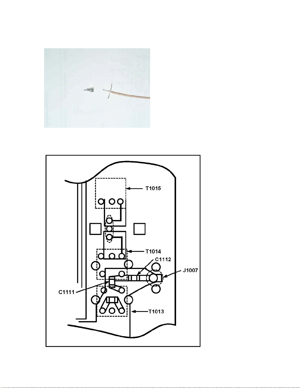
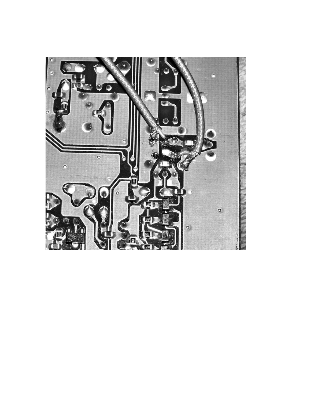
12. Locate the work area between T1013 and T1014 on the trace side of
the board. Compare it to Figure 2. Note that each transformer has 5
terminals, a group of 3 and a group of 2. T1013 and T1014 have the 2
terminal groups facing each other with C1111 making a connection
between them. Remove C1111. Use a soldering iron tip which is wide
enough to unsolder both sides of the capacitor together. A toothpick
can be used to slide the capacitor off of its pads.
13. Examine Figure 3. Dress the coax cables up and to the center of the pc
board. Connect the coax cable center conductors to the pads left open
by C1111. The pad connecting to T1013 will go to J1 on the Inrad
mod. The pad connecting to T1014 will go to J2 on the Inrad mod.
Ground the shields to the nearest ground pad.
14. Check that the soldering is secure before turning the board over.
15. Reverse the removal procedure to reinstall the PC board and shielded
assembly. Use care to align the assembly pins with their sockets
before applying any pressure.
16. Set the radio on its left side with the panel facing left. The Roofing
Filter mod board will mount on the right side of the casting which is
now facing up.
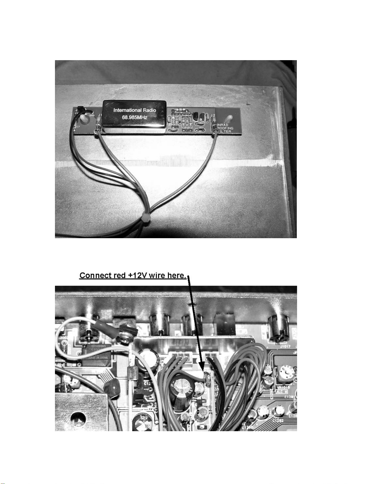
17. Prepare the mod board by soldering the red wire to the +12V pad.
Ground will return through the coax shields.
18. Press the standoffs into the mod board holes from the bottom side.
19. Remove the safety papers from the sticky ends of the standoffs and
press the mod board assembly onto the top of the radio casting as
shown in Figure 4.
© 2008 International Radio Corporation - 4 -