INNO IF44 Manuel utilisateur
IF44
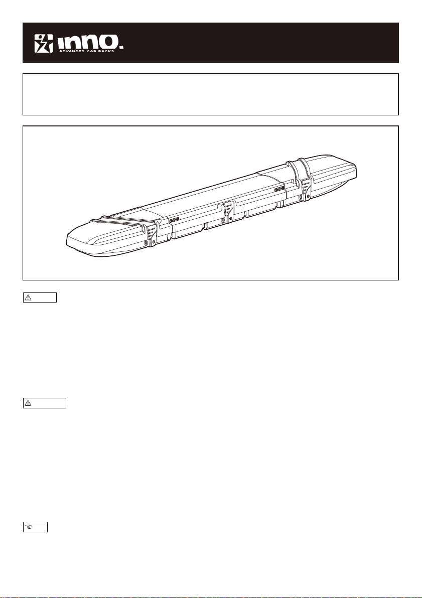
IF44 Rod Box Installation Instructions
Before using this product, carefully read this instruction manual for proper use.
Keep this instruction manual in a safe place.
If you are to give this product to a third person, provide him/her with this manual as well
to ensure safe use.
●This product is made specifically for fishing rods and those with reels attached.
Do not use for other purposes.
●Do not modify this product.
●Avoid overspeeding, sudden starts, sudden turns, and sudden braking as much as possible.
●Close the cover securely and lock with the key. Failing to do so may cause the cover to open while
driving, and the rod box to be damaged and/or to fall off the vehicle roof due to wind pressure.
●Before driving, check the two installation positions with the base carriers, and the bolted positions on
the product body are securely tightened. Re-tighten all loosely-bolted positions.
●Make sure that the vehicle rear hatch (trunk) does not hit the rod box when opening.
●The rod box is not constructed to be completely waterproof.
Loaded items may get wet due to strong rain.
●Opening and closing the rod box during strong gusts or winds may cause the box to be damaged,
or have your body trapped in the box, leading to injury.
●Always remember that the vehicle height has increased when the rack is installed.
●Remove the rack before using an automatic car wash.
●Do not use a car cover (including a cover for preventing paint splatter) with this product installed.
The rod box may deform due to weather conditions such as high temperatures.
●Do not place any items on this product. Doing so may cause cover deformation.
●The rod box materials gradually deteriorate due to exposure to UV light. If you do not plan to use the rod
box for a long period of time, store it away from direct sunlight, high temperature, and high humidity.
Failure to follow this warning can result in serious accidents including death or serious injury.
Failure to follow precautions can result in injury, damage to the product, vehicle, or load.
Before using this product, the followings should be noted.
−1−
5590627A
Warning
Precautions
Note
x1
x2
x2x2
x2
x2 x2x4
x3
x4
x4
x4 x8
x8x12
x1 x1
x1
x1
x1
x1
−2−
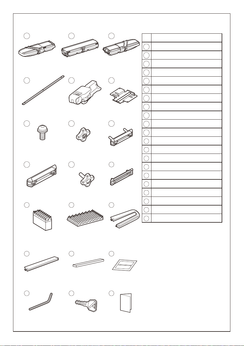
Product contents Common parts
Body A (Cover A & Bottom A hinged)
Body B (Cover B & Bottom B hinged)
Bottom plate
Joint bolt
Joint nut
Knob bolt
Knob nut
Hexagonal concave bolt *1
Filler cap *2
Grip cushion
Mold L
Mold S *2
Specification sticker
Hex Wrench
Watertight mold *3
Key
Installation instructions
Bottom cushion
Body C (Cover C & Bottom C hinged)
Frame
Memory mount
No. Part name
−2−
1
2
3
4
5
6
7
8
9
10
11
12
13
14
15
16
17
18
19
20
21
123
4 5 6
789
10 11 12
13 14 15
16 17 18
19 20 21
*1. These bolts are bolted to the frame
when the product has shipped.
Unbolt them when assembling.
*2. Two Mold Ss and two of these Filler caps
are attached to Cover A and Cover C,
respectively.
*3. Two Watertight molds are attached to
Cover A and Cover C, respectively.
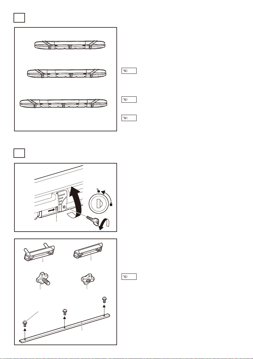
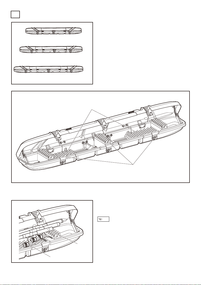
Loadable rod length
Short position
Medium position
Long position
2,200 mm (7’2” )
2,480 mm (8’1” )
2,760 mm (9’0” )
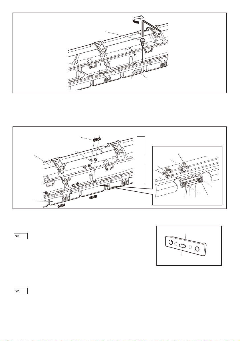
Open Cover B
1
Remove all of the joint bolts, the joint nuts,
the knob bolts and the knob nuts from the
cardboard.
Unbolt all the hexagonal concave bolts from
the frame.
2
Unlock Cover B with the key as illustrated.
Lift the lever while pressing the button.
The above lengths are the shortest for each position,
as a damper is equipped on the inside of Body A and C.
The maximum length of a loadable rod can be extended by
about 0.8 " (20 mm) depending on how you place the rod.
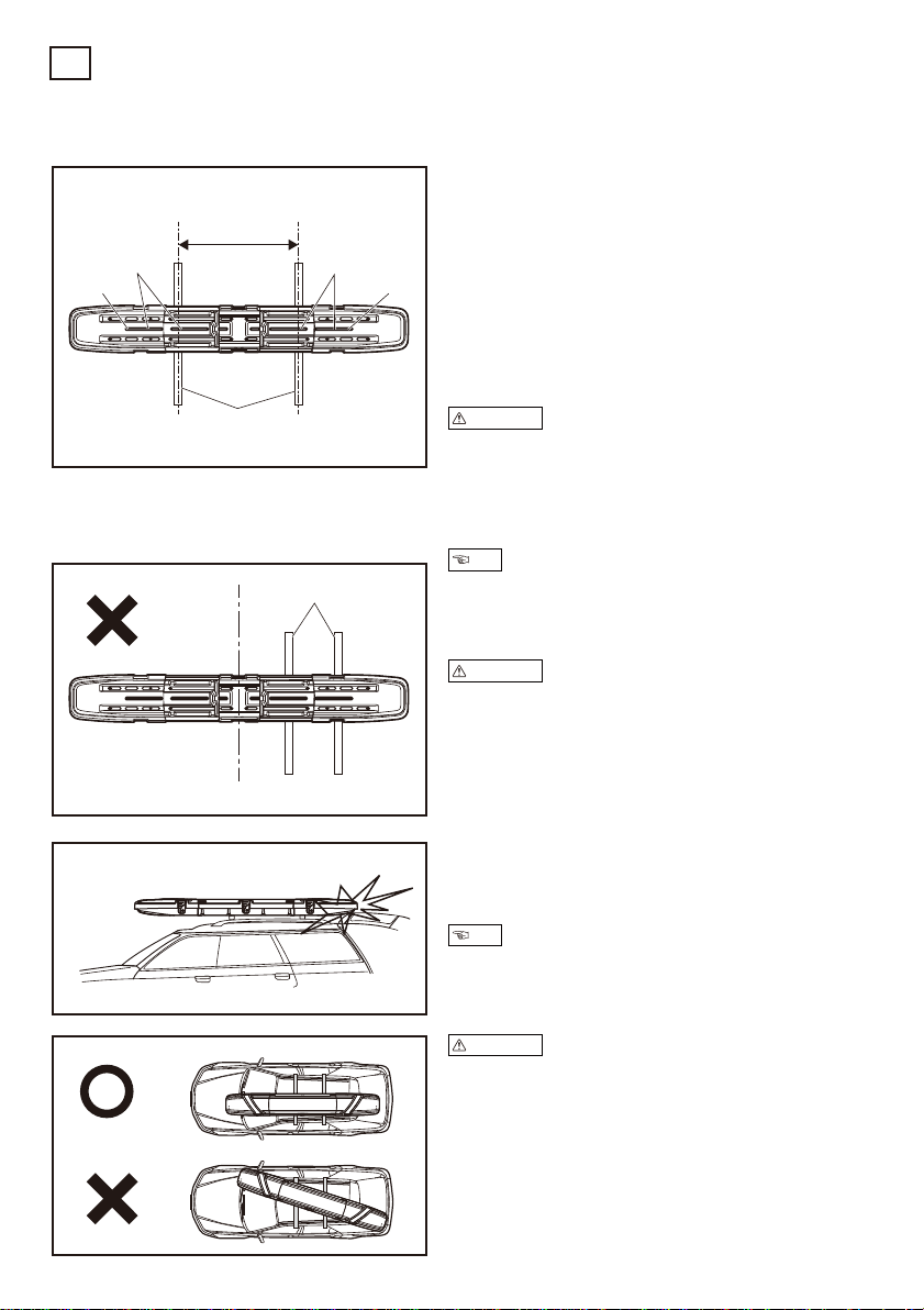
Do not use the short position if the distance between the base
racks is between 32” (810 mm) and 35” (890 mm).
Body A and C are symmetrical. As such, either edge can be
considered the front face with regard to moving direction of
the vehicle. Install with your opening/closing side facing
outward on your vehicle.
Determining a Length
1
Assembly of Body A, B and C
2
−3−
Button
Short position
Medium position
Long position
Joint bolt Joint nut
Knob bolt Knob nut
Hexagonal concave bolt
Frame
To facilitate the further assembly, group these removed parts
by type.
The length of this product can be adjusted
at three levels according to your longest rod.
Note
Note
Note
Note
OpenCoverAandC. Place themonBottomBin predeterminedlength positions.
4
Remove the filler caps on Cover A and C as necessary, depending on your position.
Short position
Medium position
Long position
5: Remove all the four filler caps from Cover A and C.
: Remove the two filler caps from the shorter Cover.*1
: Keep all the four filler caps on. *1: Cover C if installed on the left side on the vehicle
−4−
Groove
Filler cap
Cover A
Cover C
Pinch with your thumb and finger
to remove Filler cap
Groove
This illustrates Short position.
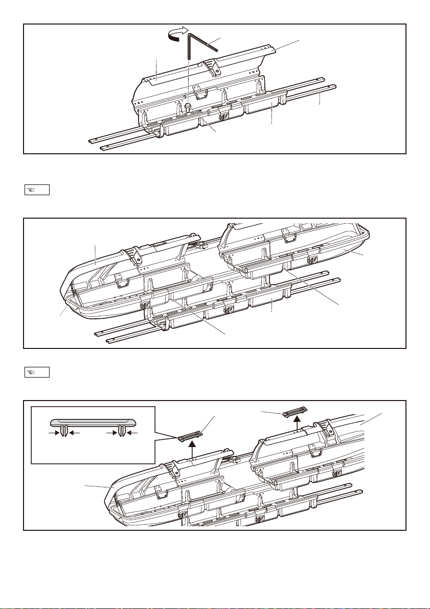
Open Cover B. Align the nut on the frame edge with the hole on Bottom B that is proximate
to the center. Loosely bolt all of four nut portions with the hexagonal concave bolt.
3
Frame
Loose bolting Cover B
Hex Wrench
Hexagonal concave bolt
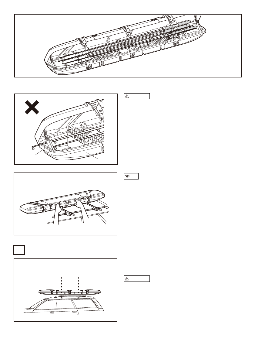
As Body B is not equipped with a damper between Cover B and Bottom B, Cover B goes freely as far back as to the
other side. When opening Cover B, take caution to avoid damage.
Engage Bottom A and C in the grooves on Bottom B as per each position.
For Medium position, ensure the Body (either A or C) on the vehicle front side is longer than the other on the rear.
Note
Note
Cover B
Body B
Bottom B
Bottom C
Cover A
Body A
Damper between
Cover A and Bottom A Bottom B
−5−
Knob bolt
Joint nut
Joint bolt
Knob nut
Cover
Bottom
Attach the four frames to Bottom A and C by firmly bolting the hexagonal concave bolts in
all the 12 locations, holding the longer end of the hex wrench to tighten.(4Nm)
6
Stick the specification sticker described in your language.
7
Hexagonal concave bolt
Specification sticker in your language
4Nm
Note
Insert the joint bolt from the outside of Cover A and C. Fixate it on the inside with the knob
nut to Cover B.
9
Align the hole on the flange portion of Bottom A and C with the convex shape on the joint
nut center. Fixate from the inside using the knob bolt.
8
Joint nut
Convex shape
When assembling each Body, start at the hinged portion to attach the joint nuts
and the knob bolts more easily.
Note
Inserting the bolts may be difficult as the joint nuts and the knob nuts have a rubber washer to prevent loosening.
When attaching, turn the knob while pressing it lightly to tighten.
Note
Body
−6−
Open the vehicle rear hatch to ensure it does
not hit the rod box. If it does, change position
of either the rod box or the base rack.
3
Confirm that the base rack is correctly
installed, and temporarily place the rod box
on the base rack.
1
Open Cover A, B and C. Adjust the position
of the product so that the slits are placed on
the base rack. If the base rack is adjusted
beneath the outer slit, remove the mold S to
install.
2
Deciding the installation position of the Rod Box
3
Base rack
Base rack
Midpoint
Distance between
the base racks
Slit
Mold S Mold S
Slit
Distance between the base racks
Short position
Medium position
Long position
24” to 31” / 35” to 55”
24” to 67”
24” to 82”
If adjustable, allow as long a distance as possible between
the base racks. A longer distance will stabilize the rod box,
and keep the vehicle cross bars under less stress.
Some vehicle types have specific installation positions of the
base rack, and touching the rear hatch is unavoidable.
Open the rear hatch carefully not to damage the rod box.
Make sure the distance between the base racks is more than
24 " (600 mm).
If the distance is too narrow, too much pressure will be
exerted on the rod box, which may cause it to fall off the
vehicle.
Ensure the midpoint of the product is aligned with right
between the base racks.
Make sure to install the rod box so that it runs parallel with the
direction of the vehicle.
Precautions
Precautions
Precautions
Note
Note
HT1
T2
−7−
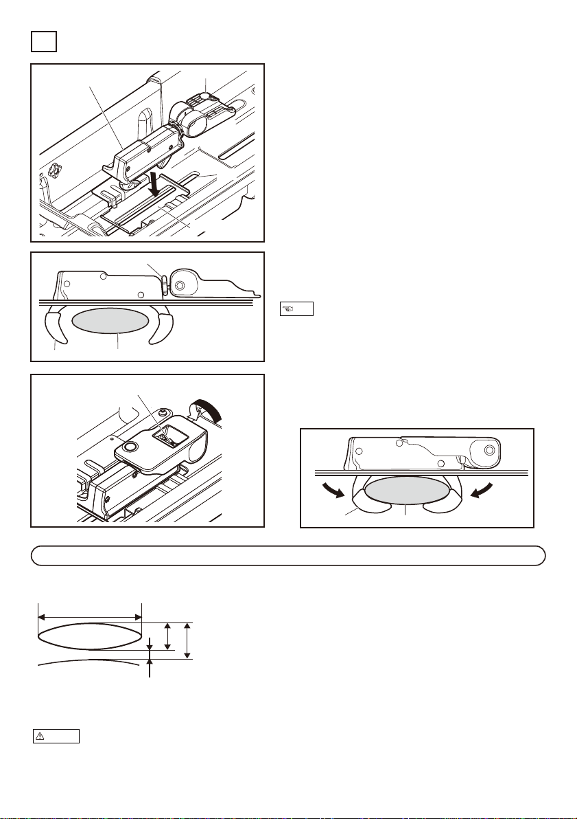
Close the lever. Turn the adjuster knob as the
arrow indicates (or clockwise) to align the
centers of both hooks and the base rack.
2
Place the bottom plate on the slit of the
base rack installation portion.
1-1
Lift the lever of the memory mount open.
Insert the hooks into the slit so they hold the
base bar.
The lever can face either direction.
1-2
If the space between the hooks is too small,
make the space wider with the adjuster
knob.
1-3
Installation of the Rod Box
4
Memory mount Lever
Base bar
Adjuster knob
Adjuster knob
Hook
Base bar
Hook
Bottom plate
Slit
Dimensions of installation hardware
H : ³⁄4” to 1 ³⁄8”
T1 : Distance to the roof
Allow minimum 2 ¹⁄8”
T2 : Allow minimum 1”
*Cannot be installed onto round bars.
1” to 3 ¹⁄2”
Mountable bar dimensions
This rod box is mountable onto genuine base racks and crossbars of the vehicle manufacturer, as
well as the INNO crossbars. Make sure to install the base rack and/or crossbars securely.
To facilitate the widening of the space, detach the memory
mount from the body.
Check vehicle or base rack product instructions to confirm that the base rack to which this product is to be installed has
sufficient strength to support this product. If the base rack does not have sufficient strength to support this product, do
not install.
Warning
Note
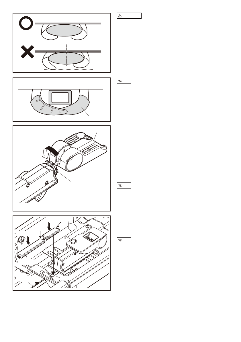
Open the lever, and rotate the adjuster knob to
the direction indicated by the arrow (counter
clockwise) by about 5 turns to make the hook
space narrower. Confirm that the base bar
center matches the center between hooks,
close the lever to securely tighten. If the lever is
loose, rotate the adjuster knob more. If the lever
is too tight, reverse the direction of the adjuster
knob and securely tighten.
3
Cut the mold L to the length of the open slit.
Press down the cut mold L into the open slit to
fill it.
4
−8−
Hook
Convex shape
Lever
Cut
Slit
Slit
Press down
Mold L
Cut
Forcefully press down the cut mold L so that its entire upper
surface is evenly flat.
When the square bar is placed, keep the tips of the hooks as
close as illustrated.
*Adjuster knob has a convex shape to indicate how many
turns are made.
*Depending on the shape of the base bar, make more or less
turns to tighten the hooks.
If the height of the 2 hooks differs, the hook center will not
match the base bar center.
Check that hooks are symmetrically positioned.
The hooks may loosen over time if they are not symmetrically
positioned.
Readjust the adjuster knob to tighten.
Precautions
Note
Note
Note
Temporarily place the grip cushions and the bottom cushions as illustrated.
1
Place your rods with their reels attached. Adjust
the loading positions of the rods.
2
Loading rods
5
−9−
Loadable rod length
Short position
Medium position
Long position
2,200 mm (7’2” )
2,480 mm (8’1” )
2,760 mm (9’0” )
Short position
Medium position
Long position
Grip cushion
Bottom cushion
Reel
Rod
Adjust so that the reels are placed on the bottom cushions.
Note
−10−
When placing multiple rods, alternate the direction of each rod's grip / tip.
3
Maximum load capacity
6
Maximum load capacity : 22 lbs.or 10 kg
Front
7.7 lbs.
(3.5 kg)
Center
6.6 lbs.
(3.0 kg)
Rear
7.7 lbs.
(3.5 kg)
Maximum 22 lbs. (10 kg)
Body A or C
Damper
Ensure the tip of the rod does not stick out of the body, or it
does not hit the damper.
If you have difficulty opening the cover, lift the two portions on
the center simultaneously shoulder-width apart.
Ensure your loads on the front, the center and the rear areas
of the rod box do not exceed their respective maximum load
capacity.
Precautions
Precautions
NoteNote
Table des matières
Manuels Matériel de pêche populaires d'autres marques

Kongsberg
Kongsberg Simrad SY50 Manuel utilisateur

Cannon
Cannon Magnum 5 ST Manuel utilisateur

Jiffy
Jiffy Pro4 Lite Manuel utilisateur

Fishmaster
Fishmaster Pro Series Guide de démarrage rapide

MIVARDI
MIVARDI Carp Scout XL Manuel utilisateur

FLAJZAR
FLAJZAR FISHTRON CatFish TX3 Manuel d'exploitation et d'entretien

Milwaukee
Milwaukee 2873-20 Manuel utilisateur

VEXILAR
VEXILAR FL-8SLT Manuel utilisateur

Fishmaster
Fishmaster Casting Platform Guide de démarrage rapide

Marcum Technologies
Marcum Technologies PanCam Manuel utilisateur

Harmony
Harmony SlideTrax 8023061 Manuel utilisateur

Quantum
Quantum Baitcast Reel Manuel utilisateur


