Installing the Easy-Mount Box Into the Wall
This section is specic to in-wall and on-wall models.
1. The in-wall and on-wall subwoofers are shipped preassembled with the faceplate attached to the easy-mount box with
bolts. In order to install the in-wall easy-mount box into the wall, you will rst need to separate the faceplate from the box. First,
remove the grille mounting anges, using the grille mounting ange driver. Note that there may be shims under some of the
grille mounting anges. You will need to save these shims to use when you reinstall the faceplate. Then unscrew the faceplate
mounting bolts using a 1/4” hex key or driver. You will later reattach the faceplate with these same faceplate mounting bolts.
2. There are two speaker wire access holes located at the top of the easy-mount box. The box comes with a solid grommet
preinstalled in the large hole and a small size grommet preinstalled in the smaller hole. The grommet hole size you will need
depends on the size of the wire you are putting through the hole. In the parts pouch you will nd a selection of large and small
grommets that have holes through them of various sizes. Use a grommet of the appropriate size to get a snug t around the
speaker wire where it enters the box. Put a solid grommet in the other hole. Make sure there is enough extra speaker wire
feeding into the box for easy handling of the loudspeaker faceplate.
3. Place the easy-mount box into the mounting hole.
4. Snug the Stud Grabber™ bolts against the left and right wall studs just enough to cause the easy-mount box to be suspended
in the cutout opening. Do not overtighten these bolts to avoid distorting the studs or box. Make all necessary adjustments to
level and position the easy-mount box in the wall. The preferred method is a small level held against the inner side of the easy-
mount box to make sure it is perfectly vertical. Upon completion, the box should be level and centered in the cutout opening
with the box gasket protruding 1/4” out from the drywall surface.
5. Tighten the Stud Grabber lock nuts with a wrench.
6. Place the 4” stud screws into the hole in the inside of the Stud Grabber bolts. Carefully pound them in about 1/4” with a
hammer to get the threads started. Tighten each of the screws with a #2 square head screwdriver until the screws are snug.
Installing the Faceplate
This section is specic to in-wall and on-wall models.
While installing the faceplate, we recommend that an assistant help hold the faceplate. Be careful working with the assembly
that you don’t damage any of the speaker components.
1. Hold the speaker faceplate up to the wall opening and attach the speaker wire to the terminal block on the back of the
faceplate, observing the proper polarity. To make the connections to the terminal block, solder or crimp with high pressure the
insulated fork terminals provided in your parts packet. Soldering is best. For in-wall, use make sure the compensator switch is
in the proper position.
2. Position the speaker faceplate over the easy-mount box. Gently move it around from side to side and up and down until
the rubber gasket slides around the faceplate mounting inserts. Screw in the faceplate mounting bolts, gently tightening each
one a little at a time, until the faceplate is approximately 1/32” from the drywall all around. DO NOT TIGHTEN THE BOLTS ANY
FURTHER. The faceplate should not contact the drywall. This avoids any vibration or distortion of the drywall.
Installing the Faceplate (cont.)
3. Install the grille mounting anges that came in the parts packet using the grille mounting ange driver. Any shims that were
removed should be replaced back under the grille mounting anges to make them level with the faceplate. The grille mounting
anges should be used even if the grilles are not, as this gives the subwoofers a nished appearance.
4. Attach the cloth grille by carefully pressing it into the grille mounting anges.
Connecting to an Amplifier
1. Be sure the amplier is turned off to avoid damage to the speakers.
2. Connect the speaker wires to the speaker outputs on your amplier. Observe proper polartity (red to red and black to black).
3. Make sure each speaker is connected to the correct amplier output (e.g. left front loudspeaker to left front output).
Installing the Subwoofer With A2 Amplifier
The A2 is designed to be used with audio/video pre-ampliers and receivers that have their own built-in low frequency crossover
circuits. These circuits typically have a low pass rolloff of 12dB/octave or 24 dB/octave. The best crossover frequency setting
is usually 60 Hz (12 dB/octave low pass) or 70 Hz (24 db/octave low pass). Ultimately, the crossover frequency setting is best
determined by consulting your own ears.
Connecting the A2 to your Amplifier / Reciever
1. Turn off the power to each piece of equipment before making any connections.
2. Using high-quality interconnect cables with RCA type terminations, connect the “SUBWOOFER OUT” on the audio/video
preamplier or receiver to “IN” on the A2. If using a single subwoofer, proceed to step 3; if using two subwoofers, skip step 3
and proceed to step 4.
3. Using high-quality speaker wire (consult the chart on page 4), connect the black binding post on the A2 to the black binding
post on the SW4.iw subwoofer and connect the red binding post on the A2 to the red binding post on the SW4.iw subwoofer.
Proceed to step 5.
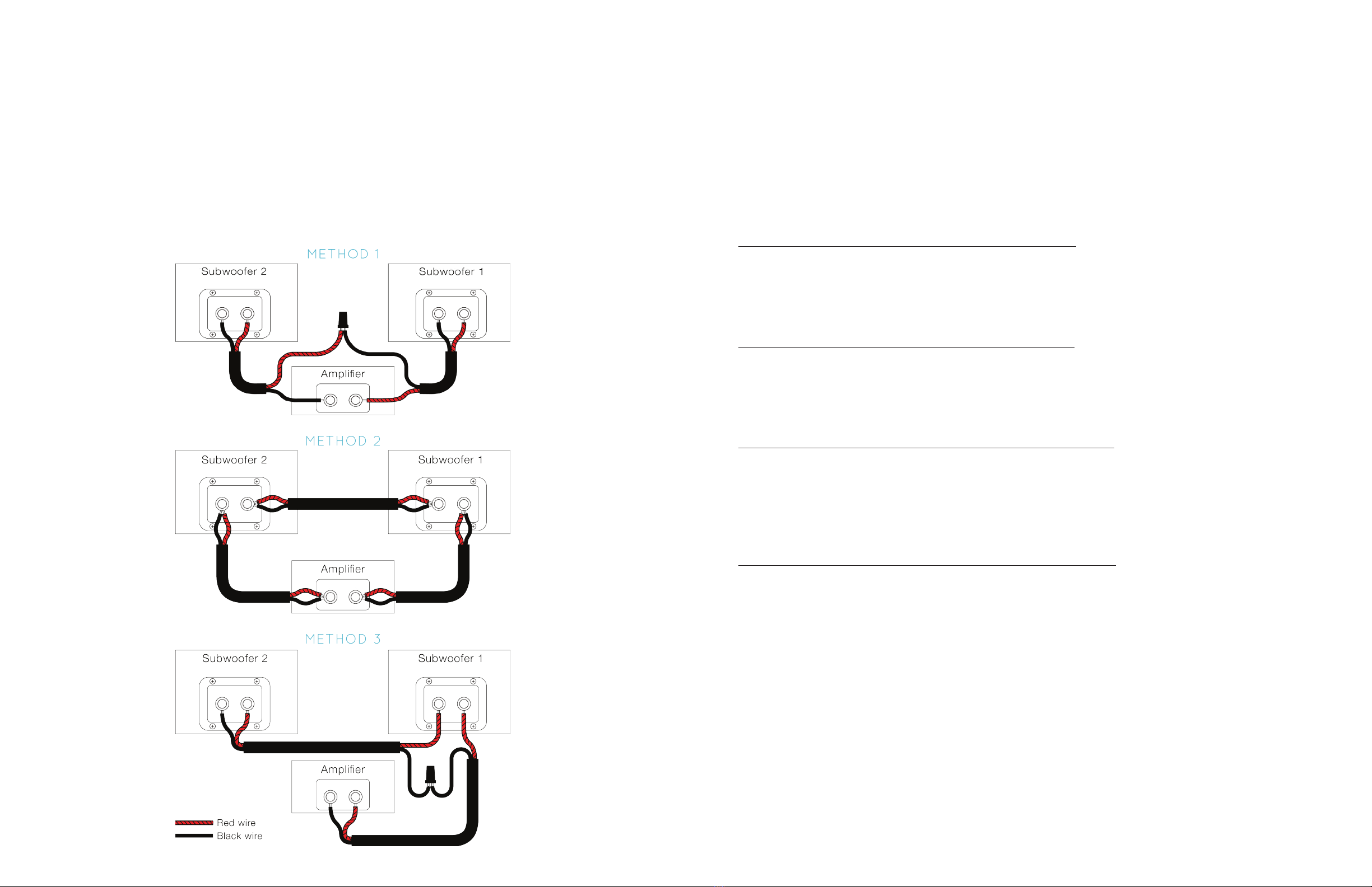
4. If using a single A2 with two subwoofers, the subs must be connected in series. In this conguration, the two 4-ohm loads
will combine to create an 8-ohm load. Connect the red binding post of the A2 amplier to the red binding post on the rst
subwoofer, and the black binding post on the A2 amplier to the black binding post on the second subwoofer. Then connect
the black binding post on rst subwoofer to the red binding post on the second subwoofer. Three subwoofer connection
methods are shown on the next page. Proceed to step 5.
5. Connect the amplier to a 120-volt, single phase, 60-Hz, grounded power supply using the power cord provided. For best
results, use a dedicated power circuit for your amplication equipment. See next page for continued steps.