Table of contents
Preface ....................................................................................Fehler! Textmarke nicht definiert.
Liability ...............................................................................................Fehler! Textmarke nicht definiert.
1. Removal and assembly instructions.................................................................................................... 3
2. Dismanteling of the carriage ............................................................................................................... 4
3. Assembly of the carriage..................................................................................................................... 7
4. Resources ............................................................................................................................................ 8
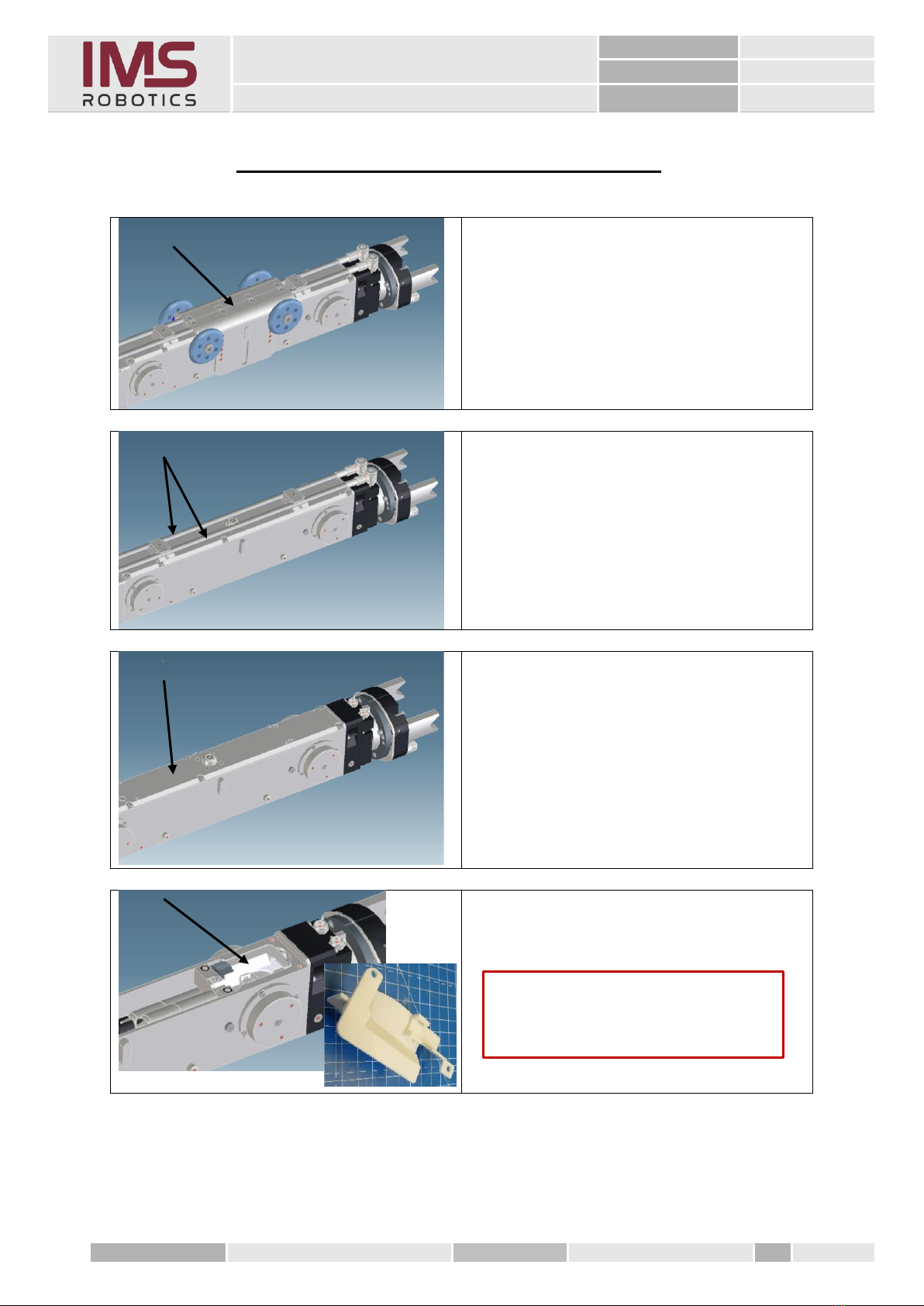
1. Removal and assembly instructions
•When dismantling the carriage to replace the drive shaft (034 11 312), the cutter arm can
and should remain mounted on the carriage. The cutter arm serves as a "lever" when pulling
the cover off the housing. Great care must be taken to ensure that the sealing surfaces and
above all, the O-ring are not damaged.
➢If the O-ring is damaged, the cutter arm must be detached from the carriage and all
cable connections disconnected. This is the only way to mount a new O-ring.
•Remove the housing cover (011 35 310) a maximum of 100 mm from the housing (011 42
623), otherwise the cabling can be damaged.
•When dismantling and assembling, always make sure that no cables or hoses are pinched or
damaged.
➢When reassembling everything must be fastened back in the same way as it was
before dismantling. (Photo documentation of the condition before dismantling)
•Check sealing surfaces and O-rings for intactness before assembly.
•When assembling, clean all sealing surfaces and bearings with brake cleaner or white spiritus
and grease again if necessary.
•Re-grease all moving parts.
•Secure all screw connections with Loctite 274 blue.