9
(R5)
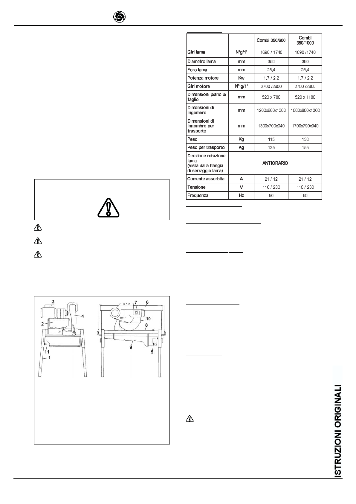
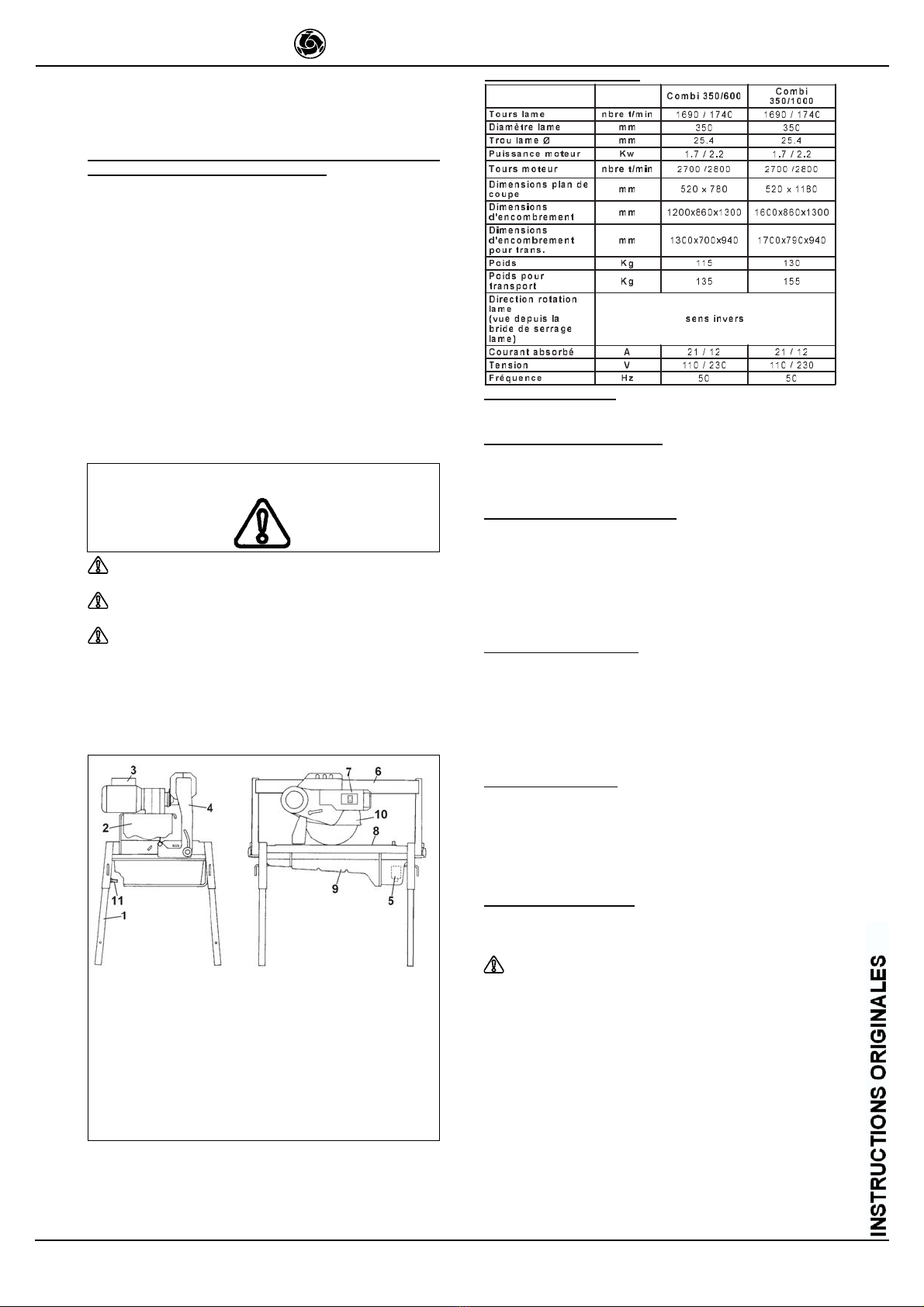
COMBI 350/600 - 350/1000
IMER INTERNATIONAL S.p.A.
and on the rating plate by the
earthing symbol.
- Stop the saw only by means of the main switch.
- he symbol shown on the label (see left) indicates
the warning ENSURE ALL PRO EC ION DEVICES
ARE INS ALLED AND IN PERFEC CONDI ION
BEFORE SWI CHING ON HE MACHINE
8. ELECTRICAL SAFETY
IMER saws comply with EN 60204-1; and are fitted with:
- protection device against automatic re-start after power failure.
- Short-circuit cutout device
- Motor overload cutout switch
9. TRANSPORTATION (Ref. Fig.2)
WARNING! Always remo e the plug from the power
socket before mo ing the saw, and lock head support carriage
mo ement by means of the relati e knob (ref. 3). To transport
the machine use slinging equipment with 4 rope legs, fixing
the hooks to the relati e attachments.
10. INSTALLATION (Ref. Fig.2)
Fix the hooks to the relative attachments on the machine and lift
the machine out of its package.
- Unlock the legs by sliding out split pins (ref.2) and pins (ref.1).
- Lock the legs at working height. Refit the pins in the leg supports
and insert the split pins.
- Install the machine on a completely even and stable surface.
11. ELECTRICAL CONNECTION
Ensure that there is an o erload cutout de ice fitted
up-line on the power line. If necessary, install an IMER quick
connect residual current circuit breaker (RCCB) (code no.
1169245 a ailable in kit form).
Ensure that the mains voltage corresponds to that specified for the
machine: 3 0 V/50 Hz (for three-phase motors) or 230 V/50 Hz
(for single-phase motors).
All power supply installations must comply with CEI 64-8
standards (harmonised document CENELEC HD384).
he electrical power cable must be suitably sized to avoid voltage
drops. Cable drums (with collector rings) must not be used.
Cable dimensions will vary according to the start-up current and
length of cable. In general cable sizes of 4 x 4 mm² are sufficient for
lengths up to 50 metres. After installation always carry out voltage
testing under load conditions, both at start-up and during operation.
During operation, voltage drops must never exceed 5%. In the case
of longer cables or a power supply network subject to variations,
use cables with a section of at least 6 mm². Cables used on
construction sites must be fitted with suitable external sheathing
that is resistant to wear, crushing and extreme weather conditions.
12. MACHINE START-UP
Before connecting the machine to the power supply:
1 - Ensure that the metal structure is connected to an earthing
plant as indicated in Section 7 Safety Precautions.
2 - Ensure that the tank contains sufficient cooling water.
3 - Ensure that the power circuit corresponds to the requirements
as indicated in Section 11 Electrical connections
4 - Connect the machine to the power supply
5 - Set the switch to 1 and when the motor is started return to
position 0 after ensuring that cooling water reaches the blade.
6 - Check that the direction of blade rotation corresponds to that
indicated by the arrow on the blade guard.
7 - ON HREE-PHASE MO OR MODELS (380 V/50 Hz): if blade
rotation is incorrect, invert the two wires inside the power plug.
Repeat operation indicated in point 5.
8 - If all is in order, proceed with cutting.
13. EMERGENCY STOP
In the e ent of emergency, stop the machine by
pressing the stop control switch.
- The motor is fitted with an o erload cutout de ice. If the motor
o erheats, it will automatically shut down. Allow motor to cool
before re-starting.
- The motor is protected against automatic re-start after
interruptions due to power failure. To resume operation, when
power is re-connected, repeat machine start-up procedure.
14. BLADE INSTALLATION (Ref.Fig.3)
By means of a hex wrench no.10, remove front screws (ref.1) and
loosen the other two screws (ref.2) which secure the blade guard.
urn the guard clockwise to gain access to the securing screw
(ref.4). Use a hex wrench no. 13 to remove the screw (turn anti-
clockwise). Remove the mobile flange and check that the flanges,
disc shaft and blade are not damaged.
Ne er use worn blades.
Only use blades that are designed for the number of
re olutions indicated on the machine rating plate.
Check that blade rotation corresponds to that
indicated on the blade guard.
Centre the blade against the fixed flange, position the mobile flange
and tighten the securing screw by means of a hex wrench no. 13
(turn clockwise). Return the guard to its original position and lock
by means of screws (ref.1 and 2).
- Ensure that the blade guard is locked securely into position.
WARNING! An incorrectly installed blade, or a screw
insufficiently tightened can pro oke damage to the machine
or injury to persons.
- Note that the blade must ha e an external diameter of 350
mm., a central hole diameter of 25.4 mm and max. thickness
of 3 mm.
- Check that the blade to be used is suitable for the material to
be cut.
15. USE
Lea e a space of 150 cm around the machine to ope-
rate in full safety.
- Do not allow other persons to approach the machine during cutting.
- Never use the machine in fire-risk areas. Sparks can cause fire or
explosions.
- Make sure that the machine is switched off before positioning or
handling.
- Always ensure that the blade is free of any contact before start-
up.
- Ensure correct installation of all protective devices.
Ensure that blade rotation corresponds to the
indications on the blade guard.
Before starting work, fill the water tank. op up during operation
whenever necessary: N.B. the pump suction hose must always
remain immersed in water.
Insert the plug in the power socket.
WARNING! For safety purposes the remo al of
protecti e guards from the machine is strictly prohibited
The machine is protected against o erload.
WARNING! Always switch off the machine before
carrying out blade adjustment.
15.1 VERTICAL BLADE MOVEMENT (Ref. Fig. 4)
o raise or lower the blade, slacken knob (ref.2) by turning it anti-
clockwise. Set blade support (ref.1) to the required position and
lock by tightening the knob fully (ref.2).
Ensure that the locking knob is tightened fully before starting
work.
15.2 BLADE POSITIONING FOR CUTS AT 45° (Ref.Fig.5)
- Slacken knobs (ref.1) on both sides of the machine. he blade
support arm (ref.2) is unlocked and so can be set to its stroke limit,
i.e. inclined at 45° with respect to the worktable. ighten the two
knobs fully to lock into position.
- o bring the blade back to the vertical position (pos.0) carry out
the above operations in reverse order.
- Ensure that the locking knobs (ref.1) are tightened fully before
starting work.
15.3 CUTTING
- Before cutting, check that the blade is aligned with the cutting
line.
- Place the workpiece on the worktable snugly against the fence.
- Start the motor and wait until the water reaches the blade to
begin cutting.
- Start cutting mo ement by pulling the carriage towards you
by means of the relati e handle (ref.1 fig.6).
- Cutting feed speed must be aried to suit workpiece thickness
and material. Cutting too fast may o erload the motor.
15.3.1 CUTS WITH BLADE LOWERED FROM ABOVE
(Ref. Fig.8)
Bring the blade support to its highest position and lock. Position
the workpiece on the worktable. Start the machine, unlock the blade
support and begin vertical cutting until the blade reaches its lowest
point. Lock the support once more and proceed with horizontal
cutting.
15.3.2. GROOVE CUTS (Ref. Fig.8)
o make shallow groove cuts, the opposite procedure to through-
GB