10781791
V a Travagl a 7
20094 CORSICO (MI)
ITALIA
Tel. 02 44 878.1
Fax 02 4503448
+39 02 45867663
www. me taly.com
nfo@ me taly.com
ISTRUMENTI MISURE ELETTRICHE SpA
I
C d. RIH4001 - RIH4002
12/ 09
Iso D4Z
10781791
FRONTALE SORVEGLIATORE RIH4
1 Display LCD
2 LED rosso s gnalazion t mp ratura/ sovraccarico pot nza TV st rno
LED int rmitt nt = pr allarm
LED acc so = allarm
3 LED giallo s gnalazion p rdita isolam nto
LED int rmitt nt = pr allarm
LED acc so = allarm
4 Tasto TEST pulsant di prova (simula una disp rsion a t rra)
5 Tasto PAGE scorrim nto pagin di visualizzazion
FRONTALE QUADRETTO RIPETITORE REMOTO
6 LED v rd s gnalazion dispositivo alim ntato
LED int rmitt nt = int rruzion comunicazion con sorv gliator
LED acc so = s gnalazion dispositivo alim ntato
7 LED rosso s gnalazion t mp ratura/ sovraccarico pot nza TV st rno
LED int rmitt nt = pr allarm
LED acc so = allarm
8 LED giallo s gnalazion p rdita isolam nto
LED int rmitt nt = pr allarm
LED acc so = allarm
9 Tasto tacitazion L’op rator ch riconosc la condizion di allarm o
pr allarm può disattivar la s gnalazion acustica pr m ndo il tasto
tacitazion .
Il tasto tacitazion agisc su tutti i rip titori coll gati.
10 TEST pulsant di prova (simula una disp rsion a t rra)
11 Avvisator acustico
Int rnitt nt ad int rvallo lungo = pr allarm
Int rmitt nt ad int rvallo br v = allarm
FACE AVANT SURVEILLEUR RIH4
1 Affich ur LCD
2 LED roug signalisation t mpératur / surcharg puissanc TP xt rn
LED clignotant = pr mièr al rt
LED allumé = alarm
3 LED jaun signalisation p rt d’isol m nt
LED clignotant = pr mièr al rt
LED allumé = alarm
4 Touch TEST touch d’ ssai (simul un défaut à la t rr )
5 Touch PAGE pour l décalag d s pag s d’affichag
FACE AVANT DU TABLEAU REPETITEUR REMOTE
6 LED v rt signalisation d dispositif alim nté
LED clignotant = int rruption d la communication av c l surv ill ur
LED allumé = signalisation d dispositif alim nté
7 LED roug signalisation t mpératur / surcharg puissanc TP xt rn
LED clignotant = pr mièr al rt
LED allumé = alarm
8 LED jaun signalisation p rt d’isol m nt
LED clignotant = pr mièr al rt
LED allumé = alarm
9 Touch d atténuation L’opérat ur qui r connaît la condition d’alarm ou
d pr mièr al rt p ut coup r la signalisation acoustiqu n appuyant sur
la touch d atténuation.
La touch d atténuation agit sur tous l s répétit urs conn ctés
10 TEST touch d’ ssai (simul un défaut à la t rr )
11 Av rtiss ur acoustiqu
Clignotant av c int rvall long = pr mièr al rt
Clignotant av c int rvall court = alarm
RIH4 SUPERVISOR FRONT FRAME
1 LCD display
2 R d LED to signal t mp ratur / xt rnal VT ov rpow r int rmitt nt
Int rmitt nt LED = pr -alarm
LED on = alarm
3 Y llow LED to signal th insulation loss
Int rmitt nt LED = pr -alarm
LED on = alarm
4 TEST k y (it simulat s a disp rsion towards ground)
5 PAGE k y to scroll th display pag s
REMOTE REPEATER SMALL SWITCHBOARD FRONT FRAME
6 Gr n LED to signal f d d vic
Int rmitt nt LED = communication int rruption with th sup rvisor
LED on = to signal f d d vic
7 R d LED to signal t mp ratur / xt rnal voltag transform r ov rpow r
int rmitt nt LED = pr -alarm
LED on = alarm
8 Y llow LED to signal th insulation loss
Int rmitt nt LED = pr -alarm
LED on = alarm
9 Sil ncing k y Th op rator who r cogniz s th alarm or pr -alarm
condition may d activat th sound signaling pr ssing th sil ncing k y.
Th sil ncing k y acts on all th conn ct d r p at rs.
10 TEST k y (it simulat s a disp rsion towards ground)
11 Horn
Int rmitt nt with long int rval = pr -alarm
Int rmitt nt with short int rval = alarm
RIH4 WÄCHTERFRONTTEIL
1 LCD-Anz ig
2 Rot LED für di Signalisi rung T mp ratur/L istungsüb rlastung d s
xt rn n VT
Blinkl d = Voralarm
LED an = Alarm
3 G lb LED für di Signalisi rung Isoli rungsv rlust
Blinkl d = Voralarm
LED an = Alarm
4 TEST-Tast (täuscht in n Erdf hl r vor))
5 PAGE-Tast für di Anz ig s it v rschi bung
FERNVERSTÄRKERSTAFELFRONTTEIL
6 Grün LED für di Signalisi rung g sp ist s G rät
Blinkl d = Kommunikation mit d m Wächt r unt rbroch n
LED an = Signalisi rung g sp ist s G rät
7 Rot LED für di Signalisi rung T mp ratur/L istungsüb rlastung d s
xt rn n VT
Blinkl d = Voralarm
LED an = Alarm
8 G lb LED für di Signalisi rung Isoli rungsv rlust
Blinkl d = Voralarm
LED an = Alarm
9 G räuschsp rr tast D r B di n r, d r d n Alarm- od r Voralarmzustand
an rk nnt, kann durch di G räuschsp rr tast das Horn ausschalt n.
Di G räuschsp rr tast wirkt auf all n ing schalt n V rstärk r
10 TEST-Tast (täuscht in n Erdf hl r vor)
11 Horn
Int rmitti r nd mit lang n Int rvall = Voralarm
Int rmitti r nd mit kurz n Int rvall = Alarm
FRONT FRAME
FACE AVANT FRONTTEIL
FRONTALI
FAULT
89
OVERLOAD
17 29
11
33
22
44
55
6688
77
99
1010
1111
RIH4
Guasto
Fault
Tacitaz. / Silence
Rete / On
Prova / Test
P
R
E
M
E
R
E
M
E
N
S
I
L
M
E
N
T
E
P
U
S
H
M
O
N
T
H
L
Y
CONTROLLO ISOLAMENTO
ARI1
INSULATION MONITOR
Sovraccarico
Overload
Montag ncastré sur un rail d 35mm, typ à chap au TH35-15, s lon EN60715.
La position d fixation n’a aucun incid nc sur l fonctionn m nt.
Avant d procéd r à l’installation, il faut vérifi r qu l s val urs d s t nsions d l’ali-
m ntation auxiliair t d la lign à surv ill r corr spond nt à c ll s rapporté s sur la
plaqu .
R sp ct r scrupul us m nt l schéma d branch m nt; un mauvais conn xion p ut
comprom ttr l corr ct fonctionn m nt ou provoqu r dommag s à l’appar il.
Un int rruption ou un court-circuit dans la conn c ion ntr l surv ill ur t l répéti-
t ur n comprom tt nt pas l fonctionn m nt du surv ill ur.
ATTENTION: si vous voul z mésur r la t mpératur du TP xt rn d isol m nt, il
faut nl v r l cavali r ntr l s born s 2 – 4 t branch r un th rmorésistanc Pt 100
(sond d témp ratur ).
Si la sond Pt 100 n’ st pas utilisé , l s val urs d témp ratur affiché s sont fictiv s.
TOUCHE TEST
Il p rm t d vérifi r l’ fficacité du surv ill ur.
Appuy r sur la touché TEST (Dans l branch m nt av c un tabl au répétit ur, t nir ap-
puyé la touché TEST jusqu’à l’av rtiss ur acoustiqu du répétit ur mit un son.
L surv ill ur simul automatiqu m nt un disp rsion v rs la t rr av c conséqu nt si-
gnalisation visu ll , acoustiqu t commutation du r lais d’alarm .
A la fin d la simulation, l’appar il va s r staur r automatiqu m nt, n r tournant n
condition d suirv illanc .
SURVEILLEUR
La programmation st prot gé par un mot d pas (1000).
CONFIGURATION
•
TC externe de mesure: rapport du TC xt rn d m sur
utilis pour m sur r la courant instantané t pour calcul r l s puissanc s.
Rapport sélectionnable: 1...9999
•
TP externe de isolement: puissanc appar nt (kVA) nominal du transformat ur
utilisé.
Puissance sélectionnable (Pn): 1,5 - 2,5 - 3 - 4 - 5 - 6,3 - 7,5 - 8 - 10kVA
•
Mesure: grand ur monitoré pour l contrôl du isol m nt.
Grandeurs sélectionnables: résistanc (R) ou bi n impédanc (Z) d’isol m nt.
ALARMES ET PREMIERE ALERTES
En phas d programmation, il st possibl insér r ou bi n xclur non s ul m nt
l’alarm pour la p rt d isol m nt mais aussi:
Premi re alerte d’isolement
Alarme + premi re alerte température du TP de isolement
Alarme + premi re alerte puissance moyenne apparente du TP de isolement
Alarm + pr mièr al rt d t mpératur t puissanc sont jum lés au mêm LED (2)
t au mêm r lais (born s 17-29).
•
PREMIERE ALERTE: L dépass m nt d la s uill d pr mièr al rt provoqu
l’allumag clignotant du LED d alarm mais il n’agit pas sur l r lais av rtiss ur.
Dans l branch m nt av c un tabl au répétit ur ARIH, la pr mièr al rt pro-
voqu un signal clignotant av c int rvall long du av rtiss ur acoustiqu .
•
ALARME: L dépass m nt d la s uill d alarm provoqu l’allumag du LED
d alarm t agit sur l r lais d sorti (born s 8-9 pour l’isol m nt ou 17-29
pour la t mpératur t/ou puissanc ).
Dans l branch m nt av c un tabl au répétit ur ARIH, la pr mièr al rt pro-
voqu un signal clignotant av c int rvall long du av rtiss ur acoustiqu .
La signalisation visu ll (LED) t l r lais d sorti av rtiss ur t/ou d pr miè-
r al rt t l r lais av rtiss ur r st nt jusq’à la résistanc / impédanc d’isol -
m nt r tourn à un val ur supéri ur à la val ur chargé .
La signalisation acoustiqu dans l tabl au répétit ur p ut êtr coupé par
l’opérat ur n agissant sur la touch d atténuation.
•
ISOLEMENT
Alarme: 50…500kΩ
Premi re alerte: Val ur alarm prè-chargé…500kΩ
•
TEMPERATURE TP ISOLEMENT
Alarme: 60…150°C
Premi re alerte: 60°C…Val ur alarm prè-chargé
ATTENTION: si on n’utilis pas la sond d t mpératur Pt100, alarm t pr mièr
al rt d t mpératur doiv nt êtr désactivés n phas d programmation.
•
PUISSANCE
Alarme: 50…100 Pn1
Premi re alerte: 50% Pn1…Val ur alarm prè-chargé
1puissanc du transfomat ur d t nsion isol m nt jum lé.
L’alarm int rvi nt sur la puissanc appar nt moy nn (pas sur la puissanc instan-
tané ) calculé sur l t mps d’intégration sél ctionné.
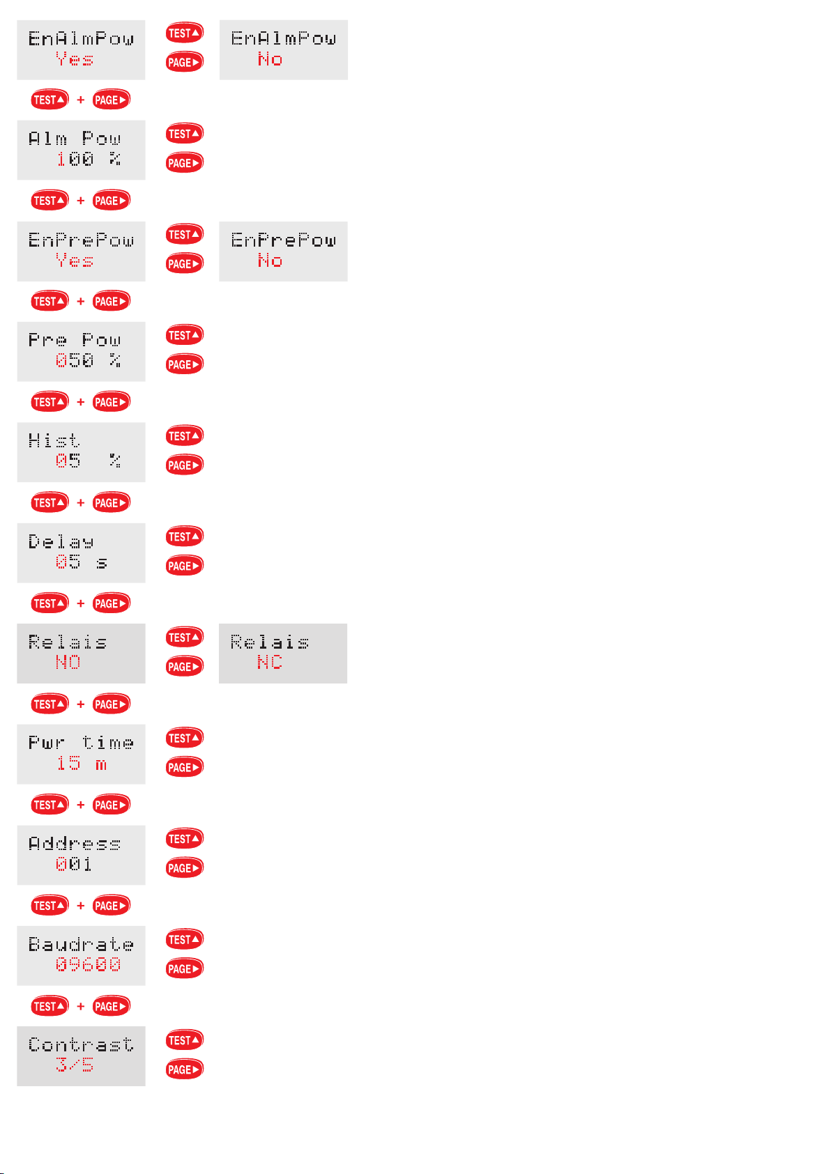
ALARMES
Hystérésis: 0…99%
Retard: 0…99 s cond s
Etat du relais: normal m nt xcité ou bi n désactivé
PUISSANCE MOYENNE
Temps d’intégration: 5 – 8 – 10 – 15 – 20 – 30 – 60 minut s
COMMUNICATION RS485
Adresse: 1…255
Vitesse de transmission: 1200 – 2400 – 4800 – 9600 – 19200 bit/s cond
PARAMETRES PROGAMMABLES
Das G rät kann auf di Normschi n 35mm, D ck ltyp TH35-15 (g m. EN60715) g -
schraubt w rd n. Di Einbaulag hat k in n Einfluss auf di Funktion.
B vor das G rät ing baut wird, müss n di W rt n d r Hilfsspannung und d r üb r-
wacht n N tz, mit d m Typ nschild v rglich n w rd n.
Falschanschluß führt zu rh blich n Anz ig f hl rn! Es könn n sogar B schädigung n
auftr t n.
Ein n Unt rbr chung od r in n Kurzschluss in di V rbindung n zwisch n d n Wä-
cht r und d n V rstärk r b inträchtigt nicht di Funktion d s Wächt rs.
ACHTUNG: w nn Si di T mp ratur d s äuß r n Isoli rungsspannungswandl r m s-
s n woll n, dürf n Si di Drahtbrück zwisch n di Kl mm n 2 – 4 abn hm n und
in n Th rmowid rstand Pt100 (T mp raturfühl r) inschalt n.
W nn Si d n Fühl r Pt100 nicht b nutz n, sind di darg st llt T mp ratursw rt
falsch.
TEST-TASTE
Es g statt t di Prüfung d r L istungsfähigk it d s Wächt rs.
Drück n Si di TEST-Tast (In di Kopplung mit in m V rstärk rstaf l, halt n Si di
TEST-Tast bis wann das Horn d s V rstärk rs in n Klang ausstoß n, g drückt.). D r
Wächt r automatisch vortäuscht in Erdschluss mit kons qu nt m Schallz ich n und
visu ll n Signalisi rung sowi di Umschaltung d s Alarmr lais.
Am End d r Simulation st llt das G rät automatisch zurück und k hrt in Üb rwachun-
gszustand zurück.
WÄCHTER
Di Programmi rung ist von in m Digitalzugriffsk nnwort g schützt (1000).
KONFIGURATION
•
Externer Messung-CT: V rhältnis d s xt rn n M sspannungswandl r, für di
M ssung d s Aug nblicksstrom s und di R chnung d r L istung n b nutzt.
Wählbares Verhältnis: 1…9999
•
Externer Isolierungs-VT: N nnsch inl istung (kVA) d s b nutzt n Wandl r.
Wählbare Leistung (Pn): 1,5 - 2,5 - 3 - 4 - 5 - 6,3 - 7,5 - 8 - 10kVA
•
Messung: Üb rwacht Größ , um di Isoli rung zu kontrolli r n
Wählbar Größ n: Isoli rungswid rstand (R) od r – Imp danz (Z)
ALARME UND VORALARME
Auß r d n Isoli rungsv rlustalarm, kann man währ nd d r Programmi rung in- od r
ausschalt n:
Isolierungsvoralarm
Alarm + Vorlarm für die Isolierungsspannungswandlerstemperatur
Alarm + Vorlarm für mittlere Scheinleistung des Isolierungsspannungswandler
T mp ratur- und L istungsalarm + Voralarm sind mit d r gl ich n LED (2) und mit d m
gl ich n R lais (Kl mm n 17-29) g kopp lt.
•
VORALARM: Di Voralarmschw ll üb rschr itung v rursacht di Blink inschaltung
d r Alarml d ab r wirkt nicht auf das Alarmr lais.
In di Kopplung mit in m ARIH-V rstärk rstaf l, v rursacht d n Voralarm in
Blinksignal d s Horn s mit lang n Int rvall.
•
ALARM: Di Alarmschw ll üb rschr itung v rursacht di Einschaltung d r Alarml d
und wirkt auf das Ausgangsr lais (Kl mm n 8-9 für di Isoli rung od r 17-29 für
T mp ratur und/od r L istung).
In di Kopplung mit in m ARIH-V rstärk rstaf l, v rursacht d n Voralarm in
Blinksignal d s Horn s mit kurz n Int rvall.
Di S hsignalisi rung (LED), das Alarm- und/od r Voralarmausgangsr lais und das
Alarmr lais bl ib n bis wann di Isoli rungswid rstand / -Imp danz k hrt zu in r
W rt groß r als di g lad n W rt zurück.
Das Horn in d n V rstärk rstaf l kann von d m B di n r durch di G räuschsp rr -
tast ausg schalt t w rd n.
•
ISOLIERUNGSSPANNUNGSWANDLER
Alarm: 50…500kΩ
Voralarm: G lad n r Alarmw rt…500kΩ
•
ISOLIERUNGS VT TEMPERATUR
Alarm: 60…150°C
Voralarm: 60°C…G lad n r Alarmw rt
ACHTUNG: w nn Si d n Pt100 T mp raturfühl r nicht b nutzt, müss n d r
T mp raturalarm und –Voralarm währ nd d r Programmi rung g sp rrt w rd n
•
LEISTUNG
Alarm: 50…100%Pn1
Voralarm: 50%Pn1…G lad n r Alarmw rt
1N nnl istung d s g kopp lt n Isoli rungsspannungswandl r.
D r Alarm gr ift auf di mittl r Sch inl istung (nicht auf di Aug nblicksl istung)
in. Di mittl r Sch inl istung ist auf di g wählt Int grationsz it g r chn t.
ALARME
Hysteresis: 0…99%
Verzögerung: 0…99 S kund n
Relaiszustand: normal rw is rr gt od r abg fall n
MITTLERE LEISTUNG
Integrationszeit: 5 – 8 – 10 – 15 – 20 – 30 – 60 Minut n
RS485 KOMMUNIKATION
Adresse: 1…255
Übertragungsgeschwindigkeit: 1200 – 2400 – 4800 – 9600 – 19200 Bit/S kund n
PROGRAMMIERBARE PARAMETER
INSTRUCTIONS POUR L’INSTALLATION INSTALLATION
Montaggio a incastro su profilato 35mm, tipo a capp llo TH35-15, s condo EN60715
La posizion di fissaggio risulta compl tam nt indiff r nt ai fini d l funzionam nto.
Prima di proc d r alla installazion , v rificar ch i valori d ll t nsioni d ll’alim nta-
zion ausiliaria d lla lin a sorv gliata, corrispondano a qu lli riportati in targa.
Risp ttar scrupolosam nt lo sch ma d’ins rzion , una in satt zza n i coll gam nti
può pr giudicar il corr tto funzionam nto o causar danni all’appar cchio.
Una int rruzion o un corto circuito n i coll gam nti tra sorv gliator rip titor non
pr giudica il funzionam nto d l sorv gliator .
ATTENZIONE: n l caso si voglia misurar la t mp ratura d l TV st rno di isola-
m nto, occorr rimuov r il cavallotto tra i mors tti 2 - 4 coll gar una t rmor si-
st nza Pt100 (sonda di t mp ratura).
S non vi n utilizzata la sonda Pt100, i valori di t mp ratura visualizzati sono fittizi.
TASTO TEST
Cons nt di v rificar l’ ffici nza d l sorv gliator .
Pr m r il pulsant TEST (N ll’abbinam nto con un quadr tto rip titor , t n r pr -
muto il tasto TEST fino a quando l’avvisator acustico d l rip titor m tt un suono).
Il sorv gliator provv d automaticam nt a simular una disp rsion v rso t rra con
cons gu nt s gnalazion visiva, acustica commutazion r lè di allarm .
Al t rmin d lla simulazion l’appar cchio si ripristina autonomam nt , ritornando in
condizion di sorv glianza.
SORVEGLIATORE
La programmazion è prot tta da password num rica (1000).
CONFIGURAZIONE
•
TA esterno di misura: rapporto TA st rno di misura utilizzato p r la misura d lla
corr nt istantan a d il calcolo d ll pot nz .
Rapporto selezionabile: 1...9999
•
TV esterno di isolamento: pot nza appar nt (kVA) nominal d l trasformator
utilizzato.
Potenza selezionabile (Pn): 1,5 - 2,5 - 3 - 4 - 5 - 6,3 - 7,5 - 8 - 10kVA
•
Misura: grand zza monitorata p r il controllo d ll’isolam nto
Grandezze selezionabili: r sist nza (R) o imp d nza (Z) d’isolam nto
ALLARMI E PREALLARMI
Oltr all’allarm di p rdita isolam nto, è possibil ins rir o sclud r in fas di
programmazion :
preallarme di isolamento
allarme + preallarme temperatura TV isolamento
allarme + preallarme potenza media apparente TV isolamento
Allarm pr allarm di t mp ratura pot nza sono abbinati allo st sso LED (2) allo
st sso r lè (t rminali 17-29).
•
PREALLARME: Il sup ram nto d lla soglia di pr allarm , causa l’acc nsion
int rmitt nt d l LED di allarm ma non agisc sul r lè di allarm .
N ll’abbinam nto con un quadr tto rip titor ARIH, il pr allarm causa anch un
s gnal int rmitt nt ad int rvallo lungo d ll’avvisator acustico.
•
ALLARME: Il sup ram nto d lla soglia di allarm , causa l’acc nsion d l LED di
allarm agisc sul r lè di uscita (t rminali 8-9 p r isolam nto oppur 17-29 p r
t mp ratura /o pot nza).
N ll’abbinam nto con un quadr tto rip titor ARIH, il pr allarm causa anch un
s gnal int rmitt nt ad int rvallo br v d ll’avvisator acustico.
La s gnalazion visiva (LED) d il r lè di uscita di allarm /o pr allarm d il r lè di
allarm p rmangono fino a quando la r sist nza / imp d nza di isolam nto ritorna
ad un valor sup rior a qu llo impostato.
La s gnalazion acustica n l quadr tto rip titor può ss r disattivata dall’op ra-
tor ag ndo sul tasto di tacitazion .
•
ISOLAMENTO
Allarme: 50...500kΩ
Preallarme: Valor allarm impostato...500kΩ
•
TEMPERATURA TV ISOLAMENTO
Allarme: 60...150°C
Preallarme: 60°C...Valor allarm impostato
ATTENZIONE: s non si utilizza la sonda di t mp ratura Pt100, allarm pr allarm
di t mp ratura d vono ss r disabilitati in fas di programmazion .
•
POTENZA
Allarme: 50...100%Pn1
Preallarme: 50%Pn1...Valor allarm impostato
1 Pot nza nominal TV isolam nto abbinato.
L’allarm int rvi n sulla pot nza appar nt m dia (non sulla pot nza istantan a),
calcolata sul t mpo di int grazion s l zionato.
ALLARMI
Isteresi: 0...99%
Ritardo: 0...99 s condi
Stato rel : normalm nt ccitato o dis ccitato
POTENZA MEDIA
Tempo integrazione: 5 - 8 - 10 - 15 - 20 - 30 - 60 minuti
COMUNICAZIONE RS485
Indirizzo: 1...255
velocità trasmissione: 1200 - 2400 - 4800 - 9600 - 19200 bit/s
35 mm. rail DIN flush mounting, TH35-15 cap-typ , according to EN60715.
Working is not aff ct d, in any way, by th mounting position.
B for mounting, pl as mak sur that th valu s of th voltag s of th auxiliary
supply as w ll as th lin to b monitor d corr spond to th on s r port d on th
lab l.
Scrupulously r sp ct th wiring diagram; an rror in conn ction may ndang r th
prop r working or caus damag s to th d vic .
A br akdown or a short circuit in th conn ctions b tw n th sup rvisor and th r -
p at r do s not ndang r th sup rvisor working.
ATTENTION: in th v nt you want to m asur t mp ratur of th xt rnal isolation
VT, you hav to r mov th jump r b tw n 2 and 4 t rminals and conn ct a Pt100 r -
sistanc bulb (t mp ratur s nsor).
If a Pt100 s nsor is not us d, th display d t mp ratur valu s ar fictitious.
TEST KEY
It allows v rifying th ffici ncy of th sup rvisor.
Pr ss TEST k y (Combin d with a small r p at r switchboard, k p pr ss d TEST k y
until th r p at r horn giv s out a sound).
Th sup rvisor automatically simulat s a l akag towards ground with cons qu nt vi-
sual and sound signaling tog th r with th switching of th alarm r lay.
At th nd of th simulation, th m t r automatically r s ts, r turning in th monito-
ring condition.
SUPERVISOR
Th programming is prot ct d by a num ric password (1000).
CONFIGURATION
•
External instrument CT: xt rnal instrum nt CT ratio us d to m asur th mom n-
tary curr nt and to calculat th pow rs.
Selectable ratio: 1…9999
•
External isolation VT: rat d appar nt pow r (kVA) of th us d transform r.
Selectable power (Pn): 1,5 – 2,5 – 3 – 4 – 5 – 6,3 – 7,5 – 8 – 10kVA
•
Measurement: monitor d quantity to ch ck th insulation.
Selectable quantities: insulation r sistanc (R) or imp danc (Z).
ALARMS AND PRE-ALARMS
B sid s th insulation loss alarm, it is possibl to add or bypass during th program-
ming:
insulation pre-alarm
isolation VT temperature alarm + pre-alarm
isolation VT apparent average power alarm + pre-alarm
T mp ratur and pow r alarm + pr -alarm ar link d to th sam LED (2) and th
sam r lay (t rminals 17-29).
•
PRE-ALARM: Exc ding th pr -alarm thr shold, caus s th int rmitt nt
turning on of th alarm LED without acting on th alarm r lay.
Combin d with an ARIH small r p at r switchboard, pr -alarm caus s also a long-
int rval int rmitt nt signal giv n out by th horn.
•
ALARM: Exc ding th pr -alarm thr shold, caus s th turning on of th alarm
LED acting on th output r lay (t rminals 8-9 for insulation or 17-29 for t mp ratu-
r and/or pow r).
Combin d with an ARIH small r p at r switchboard, pr -alarm caus s also a short-
int rval int rmitt nt signal giv n out by th horn.
Th visual signaling (LED), th alarm and/or pr -alarm output r lay and th alarm
r lay stay until th insulation r sistanc /imp danc r turns to a valu high r than
th load d on .
Acting on th sil ncing k y, th op rator can d activat th sound signaling in th
small r p at r switchboard.
•
INSULATION
Alarm: 50...500kΩ
Pre-alarm: Pr -load d alarm valu ...500kΩ
•
INSULATION VT TEMPERATURE
Alarm: 60...150°C
Pre-alarm: 60°C...Pr -load d alarm valu
ATTENTION: if you do not us th Pt100 t mp ratur s nsor, t mp ratur alarm
and pr -alarm must b d activat d during programming
•
POWER
Alarm: 50...100%Pn1
Prealarm: 50%Pn1...Pr -load d alarm valu
1Rat d pow r of th conn ct d isolation VT.
Th alarm trips on th av rag appar nt pow r (not on th instantan ous pow r)
calculat d on th s l ct d d lay tim .
ALARMS
Hysteresis: 0..99%
Delay: 0…99 s conds
State of the relay: normally n rgiz d or d - n rgiz d
AVERAGE POWER
Delay time: 5 – 8 – 10 – 15 – 20 – 30 – 60 minut s
RS485 COMMUNICATION
Address: 1…255
Transmission speed: 1200 – 2400 – 4800 – 9600 – 19200 bit/s cond
PROGRAMMABLE PARAMETERS
ISTRUZIONI PER L’INSTALLAZIONE MOUNTING INSTRUCTIONS
PARAMETRI PROGRAMMABILI