
IGM Laguna SuperMax Manuel utilisateur

Manufacturer / Hersteller / Výrobce / Výrobca / Manufacturer / Gyártó:
Laguna Tools Inc
2072 Alton Pkwy
Irvine, CA 92606,
USA
Phone: +1 800-234-1976
Website: www.lagunatools.com
Distributor / Distributor / Distributor / Distribútor / Distributor / Forgalmazó:
IGM nástroje a stroje s.r.o.
Ke Kopanině 560, 252 67, Tuchoměřice, Praha-západ
Česká republika
+420 220 950 910
Email: [email protected]
www.igm.cz
71632 2017-08
Drum Sander
Zylinderschleifmaschine
Válcová bruska
Valcová brúska
Hengeres csiszoló
Szlierka walcowa
1632
man_151-1632_A4ob_Válcová bruska_EN+DE+CZ+SK+HU+PL_v1.4
EN Operating instructions
(Translation of original)
DE Gebrauchsanweisung
(Übersetzung der Original gebrauchsanweisung)
CZ Návod k obsluze
(překlad původního návodu)
SK Návod na obsluhu
(preklad pôvodného návodu)
HU Használati útmutató
(eredeti használati útmutató fordítása)
PL Instrukcja obsługi
(tłumaczenie oryginalnej instrukcji)

-2-www.igmtools.com
CE-Conformity Declaration
Product: SuperMax Drum Sander
16-32
Type number: 71632
Brand: Laguna
Manufacturer:
Laguna Tools
2072 Alton Parkway, Irvine, CA 92606, USA
We hereby declare that this product complies with these regulations:
* 2006/42/EC Machinery Directive
* 2004/108/EC EMC Directive (Electra Magnetic Compatibility)
* 2006/95/EC Low Voltage Directive
* 2002/95/EC RoHS Directive (Reduction of Hazardous Substances)
Designed in consideration of the standards:
**EN ISO 12100-1, EN ISO 12100-2, EN ISO 13857, EN 349, EN 953,
EN 60204-1, EN ISO 13849-1, EN ISO 11202, EN ISO 14121-1
Responsible for technical documentation:
Torben Helshoj, President
Laguna Tools, 2072 Alton Parkway. lrvine, CA 92606
2020-09 Ivo Mlej, CEO
IGM nástroje a stroje s.r.o., Ke Kopanině 560, 252 67 Tuchoměřice, Česká republika

-3-www.igmtools.com
Table of Contents
1. Declaration of Conformity
2. Warranty
3. Safety
Authorized Use
General Safety Notes
Hazards
Grounding Instructions
4. Machine Specication
5. Transport and Setup
Setup
6. Setting and Adjustment
Drum Sander Adjustment
Installing and Wrapping Abrasives
7. Machine Operation
8. Maintenance
9. Troubleshooting
1. Declaration of Conformity
We declare that this product is in compliance with the directive and the
standard mentioned on the previous page of this manual.
2. Warranty
The company IGM Tools & Machinery s.r.o. always strives to deliver a
product of high quality and efciency.
The application of the warranty is governed by the valid Business
Conditions and the Warranty Conditions of the company IGM Tools &
Machinery s.r.o.
3.Safety
3.1 Authorized Use
This machine is designed for sanding wood and wooden products only.
Sanding of other materials is not permitted but can be performed in
specic cases only after consulting the manufacturer.
The machine is not suitable for wet sanding.
The required minimum age must be observed.
The machine must only be used in a technically perfect condition.
In addition to the operating instructions, also read the safety requirements
and your country’s applicable regulations.
You should observe the generally recognized technical rules and safety
requirements concerning the operation of woodworking and metalworking
machines.
Neither the manufacturer nor the supplier is liable for damage resulting
from unauthorized use of the machine. Responsibility is transferred
exclusively to the operator.
3.2 General Safety Notes
Woodworking machines can be dangerous if not used properly.
Read and understand the entire operating manual before attempting
assembly or operation.
Protect this operating manual from dirt and humidity and pass it over to the
new owner if you part with the machine.
No changes to the machine may be made.
Daily inspect the function and existence of the safety appliances before
you start the machine. Correct all defects or damaged safety appliances
immediately. The machine must only be used in a technically perfect
condition.
Protect long hair with a cap or hair net. Remove all loose clothing, rings,
watches and other jewellery. Wear safety shoes; never wear leisure shoes
or sandals. Follow personal protection guidelines.
Do not wear gloves while operating this machine!
Install the machine so that there is sufcient space for safe operation and
workpiece handling.
The machine must be bolted on rm and levelled surface and must be
properly lighted.
Always wear a protective mask in a dusty environment.
Keep work area well lighted.
Make sure the machine stands on a board.
Make sure that the power cord does not impede work. Keep work area
clean. Never reach into the machine while it is operating or running down.
Stay alert! Give your work undivided attention. Use common sense. Do
not operate the machine under the inuence of drugs, alcohol or any
medication.
Keep children and visitors a safe distance from the work area. Never
leave a running machine unattended. Before you leave the workplace
switch off the machine.
Do not use the machine in a dump environment and do not expose it to
rain.
Wood dust is explosive and can also represent a risk to health. In
particular dust from tropical woods and hardwoods like beech and oak, is
classied as a carcinogenic substance.
Focus on the position of your ngers and other parts of your body when
working.
Do not start the machine without safety appliances.
It is important to clamp all workpieces.
Machine only stock which rests securely on the table.
Do not remove chips and workpiece parts until the machine is at a
standstill.
Minimum workpiece length is 60 mm.
Do not stand on the machine.
Repair work on the electrical installation may be carried out by a qualied
electrician only.
Have a damaged or worn power cord replaced immediately.
Have a damaged abrasive replaced immediately.
3.3 Hazards
When using the machine according to regulations some remaining
hazards may still exist.
EN - English
Operating Instructions (Original)
Dear Customer,
many thanks for the condence you have shown in us with the purchase of your new Laguna Tools machine. This manual has been
prepared for the owner and operators of an IGM LAGUNA 1632 SuperMax Drum Sander to promote safety during installation,
operation and maintenance procedures. Please read and understand the information contained in these operating instructions and the
accompanying documents. To obtain maximum life and efciency from your machine, and to use the machine safely, read this manual
thoroughly and follow instructions carefully.
We wish you many work and personal pleasures when working with the Laguna Tools machine.

-4-www.igmtools.com
Loose sanding belt can cause injury. The workpiece may bounce off the
sanding belt and turn against the machine operator.
Danger of thrown workpiece.
Dust and noise can be health hazards.
Be sure to wear safety goggles, ear protection and dust mask.
Use a suitable dust exhaust system.
Defective or damaged sanding belt can cause injury.
Do not use damaged or worn power cord.
3.4 Grounding Instructions
Connection cord:
In the case of a defect or malfunction, grounding provides a path of least
resistance to electric current, reducing the risk of electric shock. The
machine is supplied with connection cord with a guard wire and euro plug.
The plug must only be connected to an appropriate outlet in accordance
with all local codes and regulations.
• Do not modify the plug, if it does not t into the socket. Contact a
qualied electrician and have the appropriate socket installed.
• Improper connection may result in a risk of electric shock. Ground wire
is an insulated wire with a green surface with/without yellow stripes. If the
cord or plug needs to be repaired, contact a qualied electrician.
• Damaged cords should be repaired immediately and only by a qualied
electrician.
• Use only three-wire cables with a euro plug and an appropriate socket.
4. Machine Specication
Type: 1632
Power: 230 V / 50 Hz / 1 phase
Recommended circuit breaker: 16 A, rating C (16/1/C)
Current at maximum load: 6,5 A
Power output: 1100 W
Conveyor Belt Motor: 40 W
Speed: 1420 RPM
Feed Speed: 0-3 m/min.
Workpiece Width (one pass): 406 mm
Workpiece Width (two passes): 812 mm
Thickness of Material min. / max.: 0,8-76 mm
Drum Size: 127 x 406 mm
Width of Abrasive: 76 mm
Minimum dust collector capacities: 1000 m3/h
Dust Extraction Outlet: 100 mm
Length x width x height: 860 x 560 x 1220 mm
Weight: 62 kg
Shipping Dimensions: 940 x 660 x 550 mm
Shipping Weight: 71,7 kg
Fig. 1
1. Height adjustment handle of the drum
2. Shroud
3. Digital Read-out
4. Knob to start feed conveyor and select feed rate
5. Starts and stops drum motor
6. Conveyor table
7. Tension roller contact adjustment
8. Drum carriage
5. Transport and Setup
5.1 Setup
The machine is transported in a shipping package. The machine is
designed to operate in closed rooms and must be placed stable on a
rm and levelled ground. The machine requires assembling.
Package contents
Stand box contents (found inside the main box)
Fig. 2
Fig. 3
Drum Sander Assembly
Note: For initial stand assembly secure all bolts nger tight. This will allow
for easier levelling after the sanding unit is installed on the stand. The
holes in the legs are spaced so that the short and long top braces will only
line up from one face of each leg.
1. Secure two legs to the outside of each of the two short top cross braces
using the supplied carriage bolts and ange nuts.
Fig. 4
2. Secure the two long top rails inside of the legs and on top of the short
rails.

-5-www.igmtools.com
Fig. 5
3. Note: Long rail on top of short rail and both rails inside of legs.
Fig. 6
4. Connect the second leg sub-assembly to the top long rails.
Fig. 7
5. Attach the lower cross braces to the legs. The longer cross braces
should sit on top of the short ones.
Fig. 8
6. Attach a levelling foot to the bottom of each leg (not required if installing
optional caster set).
Note: After nal assembly and sander installation, adjust the nuts on the
threads as needed to level the stand.
Fig. 9
IInstalling Drum Sander
1. For easier access to the machine, peel back the plastic liner, cut the
box at the corners, and fold down the 4 sides of the box.
Fig. 10
2. Then with the help of an assistant carefully lift the machine and set it
down on a workbench with one end hanging slightly over the edge.
Fig. 11
3. Unscrew the bolts holding the wooden packing support to the underside
of the machine, then carefully turn the machine around and repeat at the
opposite end (these bolts can be re-used to secure the unit to the stand;
extra bolts are also provided for this with the machine).
Fig. 12
4. With the help of an assistant place the machine on the stand so that the
mounting holes on the stand line up with the holes on the underside of the
machine. Remove the Styrofoam and wooden support block from under
the sanding head.
Fig. 13
5. Using the supplied 14 mm wrench bolt the machine to the stand from
underneath using the supplied hex bolts and washers.
Note: With the machine properly secured, level the stand and tighten all
its bolts.
LIFTING POINT
Drum carriage
LIFTING
POINT
Motor

-6-www.igmtools.com
11. Make sure that your power supply is adequate (230 V, circuit breaker
16 A, rating C (16/1/C)). Do not plug the machine into the power supply
until it is fully setup.
Fig. 19
6. Setting and Adjustment
6.1 Setting the Drum Sander
Checking Drum Alignment
UNPLUG THE MACHINE FROM THE POWER SOURCE!
During initial setup only. Checking the alignment is necessary to make
sure that the machine functions properly.
1. Before checking the drum alignment make sure that the fast lever
between the conveyor motor and the machine is in the up position
The conveyor table bolts on the inboard side should not be so tight that
the fast lever does not rotate – see rst note on page 17.
Fig. 20
2. Remove abrasive from the drum. Removing the abrasive ensures that
the adjustment is as accurate as possible.
Fig. 21
3. Use a at, uniform piece of wood as a thickness gauge. Set it between
the conveyor belt and the drum on the inboard (right) side of the machine.
Fig. 22
4. The tension rollers are set just below the drum enough so that material
cannot pass easily underneath. Use the height adjustment handle to lower
the head until the drum makes contact with the piece of wood. Turn on the
DRO and take note of the thickness indicated on the display.
Fig. 14
6. Screw the height adjustment knob into the handle and tighten it down.
Fig. 15
7.+ 8. Slide the digital read-out (DRO) out and install the supplied batteries
with the (+) side facing up.
Fig. 16
9. Slide the DRO fully back and plug in the cable from the machine.
Fig. 17
Installing Drum Sander (continued)
10. Plug the short power cord that is attached to the motor into the outlet
on the control panel.
Fig. 18

-7-www.igmtools.com
Fig. 23
5. Raise the head of the sander by rotating the height adjustment handle up
exactly one full turn.
Fig. 24
6. After the height has been adjusted move the piece of wood over to the
outboard side (left) and lower the head by turning the handle down exactly
one full turn until the DRO thickness matches the noted thickness from
step #4.
Fig. 25
7. Check the height of the drum in relation to the piece of wood. It the
drum is aligned it will just make contact with the wood as it did on the
inboard side. If you cannot turn the handle one full turn, or if there is a
gap between the drum and the wood, proceed to the following alignment
procedure
Fig. 26
8. If the drum is not parallel, loosen the 4 socket head screws (A) along
the outboard (left) side of the conveyor belt and raise or lower the
conveyor with the adjustment nut (B) to achieve parallel alignment. Then
tighten the 4 socket head screws.
Fig. 27
Connecting Dust Collection
Dust collection is necessary for the drum sander. The sander comes
equipped with a 100 mm (4”) diameter dust exhaust port at the top of
the cover. Make sure that the minimum dust requirements are sufcient.
To attach to your collection system, install 100 mm (4”) hose from your
collector. The minimum recommended dust collector capacities is 1000
m³/h. For best results, follow the recommendations of the manufacturer
of your dust collector. When connecting dust collector straight pipe is
preferred because it is the least restrictive for airow. If straight pipe is not
possible Y’s and elbows are preferred because they are less restrictive to
airow than T’s.
Note: Some applications will require more dust collection than the
recommended minimum.
Power and Electrical Safety
11. Make sure that your power supply is adequate (230 V, circuit breaker
16 A, rating C (16/1/C))). After the dust collection system is in place and
the drum alignment is checked your machine is ready to be powered up
and operated.
Abrasive Selection Guide
To attach the abrasive to the drum, follow the procedure below.
Grit Common Application
36 GRIT - Abrasive planing, surfacing rough-sawn boards, maximum
stock or glue removal
60 GRIT - Surfacing and dimensioning boards, trueing warped boards
80 GRIT - Light dimensioning, removal of planer ripples
100 GRIT - Light surfacing, removal of planer ripples
120 GRIT - Light surfacing, minimal stock removal
150 GRIT - Finish sanding, minimal stock removal
180 - GRIT Finish sanding only, not for stock removal
220 GRIT - Finish sanding only, not for stock removal
6.2 Installing and Wrapping Abrasives
Accurate attachment of the abrasive to the drum is critical to achieving
the machine top performance. Abrasive strips do not have to be pre-
measured. The end of the roll is rst tapered and attached to the outboard
(left) side of the drum. Then the strip is wrapped around the drum. The
second taper is made for attachment to the inboard (right) side of the
drum.
Fig. 28
Note: Pre-cut abrasives have been factory tapered to the specic width of
your drum. If you are cutting your own abrasive, use the wrap that came
on the drum as a template (abrasive side up).
Installing and Wrapping Abrasives (continued)
UNPLUG THE MACHINE FROM THE POWER SOURCE!
1. Start on the left (outboard) side of the drum. Squeeze the clip lever and
insert the tapered end of the paper into the fastener so that it uses most of
the width of the slot. Release the clip lever to securely hold the abrasive.
Drum width: 406 mm (16“)
Tip-to-tip: 2 463 mm (97“)
Abrasive ready to install: 2 311 mm (91“)
Approximately 76 mm (3“)
76 mm (3“)
400 mm (15-3/4“)
TAPERED END OF THE
ABRASIVE

-8-www.igmtools.com
Fig. 29
2. Wind the abrasive around the drum, being careful not to overlap the
windings. The tapered cut of the wrap end should follow the edge of the
drum.
Continue to wrap the abrasive in a spiral fashion by rotating the drum with
your left hand and guiding the abrasive with your right hand. Successive
windings of the wrap should be ush with previous windings without any
overlap.
Fig. 30
3. Squeeze the clip lever to open the clip and pull the take-up lever to the
top. Insert the tapered end through the slot in the inboard (right) end of the
drum.
Fig. 31
4. The take-up fastener is designed to automatically tension the abrasive
wrap. If during use the abrasive wrap stretches enough to allow the take-
up lever to reach its lowest position and no longer maintain tension on the
wrap, see Abrasive Tension Adjustment.
Note: The drum was removed to show the inboard (right) take-up fastener.
Fig. 32
Fig. 33
7. Machine Operation
Proper Abrasive Position
Position the abrasive in the slot with sufcient room between the inside
of the slot and the tapered end of the wrap to allow it to be pulled into the
drum as needed. If enough space is not left between the wrap and the
inside of the slot the take-up fastener will not operate properly.
Abrasive Tension Adjustment
The abrasive wrap may stretch enough to allow the take-up lever to reach
its lowest position. If this occurs, then the abrasive is no longer tensioned.
To x this reset the take-up lever by raising it. Push the abrasive into the
slot and then release the clip lever.
Maximizing Abrasive Longevity
We recommend a sandpaper cleaning stick to remove deposits and help
extend the life of the abrasive.
1. To use the cleaning stick, operate the sanding drum with the dust cover
open and dust collection on.
2. Hold the cleaning stick against the rotating drum and move it along the
drum surface.
3. Use a brush to remove any cleaning stick remnants before resuming
operation.
ALWAYS WEAR EYE PROTECTION WHILE PERFORMING ABRASIVE
CLEANING. TAKE ALL PRECAUTIONS TO AVOID ANY CONTACT WITH
HANDS OR CLOTHING.
Operating the Sander
Depth of Cut
Determining the depth of cut is the most important operating procedure
decision. It may take some experimentation to determine the proper depth
of cut. We recommend practicing on a scrap of wood prior to sanding a
project.
• Digital Read-Out Operation
Digital read out for sanding thickness is included as standard equipment
with this unit. A DRO offers the most precise reading of sanded thickness
and allows for accurate repeatability of a thickness. This is great when
making stock that must be an exact thickness or when matching a
thickness.
1. To operate, press the ON/OFF button and then use the IN/MM button to
select between inches or millimetres.
2. With abrasive installed, lower the drum until it touches the conveyor
belt. Then press and hold the ZERO button to calibrate the DRO to
absolute zero. The DRO is now set.
3. The ABS button selects between Absolute (ABS) or Incremental (INC)
mode. ABS mode is used to read the actual thickness of the workpiece.
INC mode is used to measure the amount of material removed from
the piece’s original thickness. It will read as a negative number. When
switching back from INC to ABS the unit will once again take its reading
from absolute zero as calibrated in step 2.
4. The SET button allows selection in level of precision from 1/32“, 1/64“,
or 1/128“.
Fig. 34
Operating the Sander (continued)
Drum Head Height Adjustments
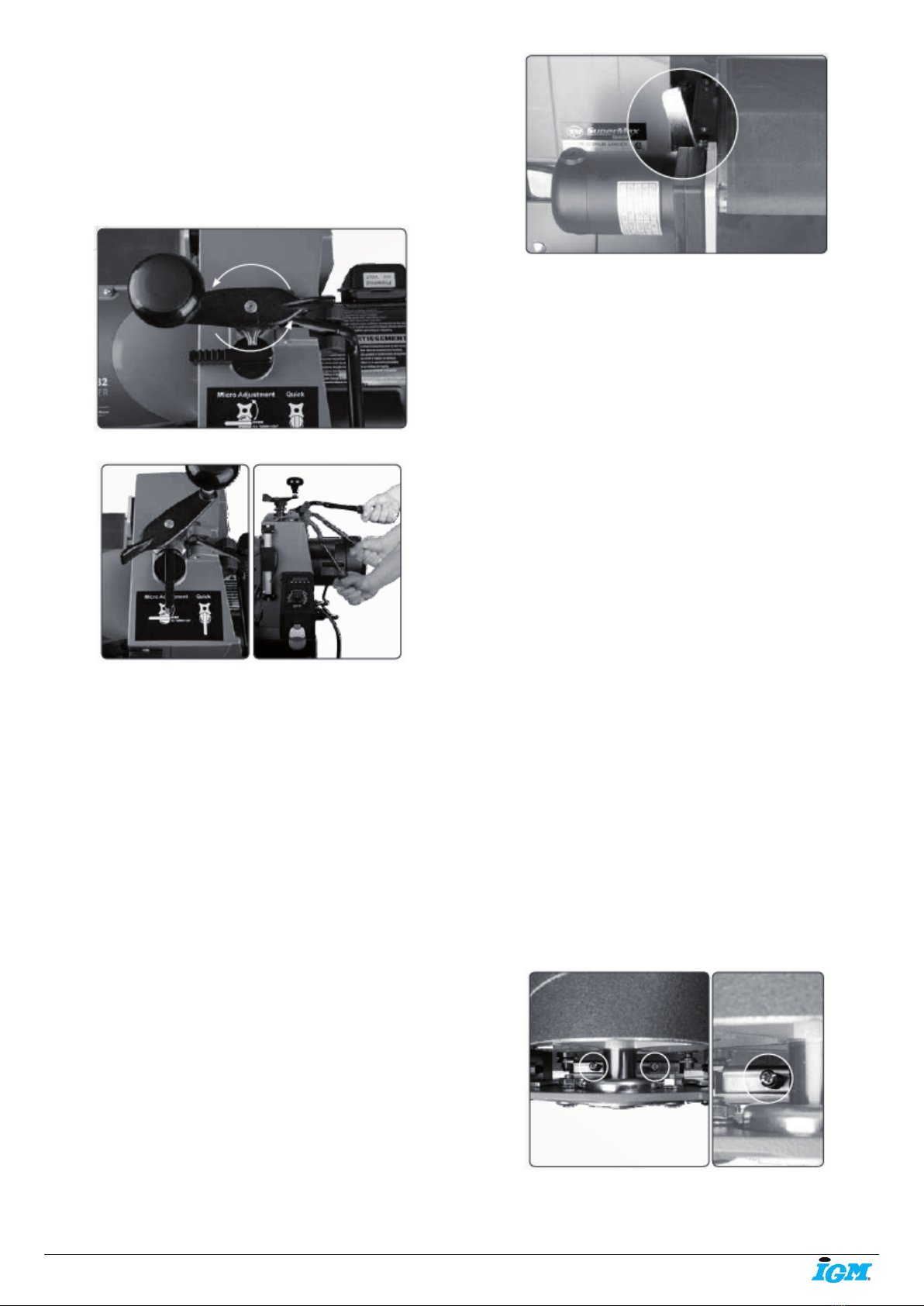
-9-www.igmtools.com
The drum height can be adjusted using one of two methods determined by
the position of the height adjustment selector.
In the micro adjustment position turning the main height adjustment
handle controls the height of the drum. Clockwise for Up and counter
clockwise for Down.
Note: One full turn raises or lowers the head approximately 1,6 mm
(1/16”).
With the selector in the quick lever position the main handle is
disengaged. Quick large-scale adjustments of up to 76,2 mm (3”) can then
be made by pulling up or down on the Quick Lever.
Note: After completing height adjustments in quick lever mode always
return the selector back to micro adjustment mode.
Fig. 35
Fig. 36
Conveyor and Speed Rate
After the depth of cut has been determined, selecting the proper feed rate
is essential. For nish sanding the best nish is usually achieved with a
slow to moderate feed rate. Faster feed rates can be used as long as the
machine is not over-stressed.
When nish sanding with grits ner than 80, the best nish can usually be
obtained if INTELLISAND does not engage. If INTELLISAND does slow
the conveyor when nish sanding, it is best to make another sanding pass
without changing the thickness setting and sand again
Note: INTELLISAND will automatically adjust the conveyor feed rate if
an excess load is detected. This prevents excessive gouging, reduces
the risk of burning and protects the machine from overload or stalling.
The red light by the adjustment knob will come on when INTELLISAND is
operating. When the load is decreased, INTELLISAND will automatically
increase the feed rate to the pre-selected speed.
Stock Feeding Operation
Rest and hold the stock to be sanded on the conveyor table. Allow the
conveyor to carry the stock into the drum. Once the stock is halfway
through, reposition yourself to the outfeed side of the machine to control
the stock as it exits the unit.
Stock Feeding Maximum Performance
The versatility of this drum sander allows it to be used for a wide range of
tasks. Learning to use the multiple controls to make adjustments will allow
you to ne tune the machine for maximum results.
Fig. 37
• Sanding stock wider than the drum
When sanding stock wider than the drum the fast lever will be very useful
(see picture). Wide stock requires extra space between the drum and the
conveyor on the outboard (left) edge. The extra space prevents ridge lines
from developing along the part that extends beyond the drum. Adjust the
fast lever 45 degrees from the vertical position to slightly shift the drum
position. Before sanding always test on a scrap piece. If a line or ridge is
still visible, make adjustments to the drum alignment. Always return the
lever to the upright position when wide stock sanding is completed.
Note: The fast lever raises the inboard side of the table .003. Upon rst
use, the conveyor table bolts may be set too tight at the factory for secure
shipping. In this case, loosen the bolts slightly. Never tighten the table
bolts all the way. Tighten the bolts enough to still allow the fast lever to be
moved.
• Sanding multiple pieces simultaneously
When sanding multiple pieces at once, make sure to stagger the pieces
across the width of the conveyor belt. This position provides better contact
with the tension rollers. It is best to only process pieces that are all of a
similar thickness. If there is a thickness difference, the thinner pieces may
not come in contact with the tension rollers and may slip on the conveyor
belt.
• Sanding Imperfect or Tall Stock
To avoid bodily injury, take special care when sanding stock that is twisted,
bowed or otherwise varied in thickness from end to end. If possible,
support such stock as it is being sanded to keep it from slipping or tipping.
Use extra roller stand, assistance from another person, or hand pressure
on the stock to minimize potentially hazardous situations. Special attention
is needed as the stock exits the machine. Special attention is needed as
the stock exits the machine.
• Stock Feeding Position and Angle
Positioning the stock at an angle will allow the most effective stock
removal and least loading on the abrasives. Feeding stock straight
through yields the widest sanding capacity and least noticeable scratch
pattern. Some pieces because of their dimensions will need to be fed into
the sander at a 90-degree angle (perpendicular to the drum). However,
even a slight offset angle of the stock can provide for more effective
sanding. Final pass sanding should be done while following the grain
pattern.
Tension Roller Pressure
The tension roller pressure is factory set and should be adequate.
However, the pressure of each roller can be adjusted as needed. To
increase the tension, turn the tension adjusting screw clockwise 1/4
revolution at a time. To decrease tension, turn the adjusting screw counter
clockwise 1/4 revolution at a time.
Note: Too little pressure can result in slippage of stock on conveyor belt or
kick-back Too much tension can cause snipe when drum sanding.
Fig. 38
Tension Roller Contact Adjustment
The tension rollers are factory set for the most versatile use.
1. To adjust tension roller contact, loosen the four socket head screws

-10-www.igmtools.com
holding the tension roller brackets (2 per side; front and back).
2. Have abrasive wrapped on the drum.
3. With the machine unplugged, lower sanding drum until it rests on
conveyor belt.
4. Raise drum 2 to 3 revolutions.
5. Tighten the four socket head screws.
6. Raise the drum up, off of the conveyor belt.
7. Set the drum on the proper sanding height.
Fig. 39
Conveyor Belt Tension
Insufcient belt tension will cause slippage of conveyor belt on the drive
roller. The conveyor belt is too loose if it can be stopped by placing your
hand directly on the conveyor belt.
Excessive belt tension can result in bent rollers, premature wearing of the
bronze bushings or conveyor belt.
To adjust the conveyor belt, rst adjust the take-up screw nut on both
sides of the conveyor to obtain approximately equal tension on both sides.
Fig. 40
Conveyor Belt Tracking
Belt tracking adjustments are made while the conveyor belt is running.
After the proper belt tension is obtained, turn the conveyor on and set it at
the fastest speed setting. Watch for a tendency of the conveyor belt to drift
to one side of the conveyor.
To adjust the belt tracking, tighten the take-up screw nut on the side the
belt is drifting toward, and loosen the take-up screw nut on the opposite
side.
Adjusting the take-up screw nuts does not affect the belt tension.
Note: Adjust the take-up screw nuts only 1/4 turn at a time. Allow the
belt to react to the adjustments before proceeding further. Avoid over-
adjustments.
Fig. 41
8. Maintenance
Monthly Maintenance
• Lubricate conveyor bushings and check for wear.
• Lubricate with a dry lubricant spray all of the moving parts.
• Clean dust from conveyor belt.
• Check all set screws for tightness.
• Clean drum and abrasives if necessary.
Replacing Conveyor Belt
To replace the conveyor belt, the conveyor assembly must be removed
from the machine.
Unplug the machine from the power source!
1. Raise the drum carriage to its highest position. Unplug main drive motor
from receptacle on the machine.
Fig. 42
2. Loosen the conveyor take-up screws to relieve belt tension and slide
the drive roller fully inward.
Fig. 43
3. Remove the two hex bolts on the inboard (right) side that attach the
conveyor assembly to the base.
Fig. 44
4. Remove the two nuts and washers from outboard (left) side. Lift the
conveyor and remove it from the sander. Set conveyor on motor side.
Avoid tearing the belt on any edges underneath the conveyor bed during
removal. Reverse the procedure for re-installation.
Fig. 45
Ce manuel convient aux modèles suivants
1
Table des matières
Langues :
Autres manuels IGM Sander


