Hydrofarm Autopilot APCEM2 Manuel utilisateur

INSTRUCTIONS
DIGITAL CO2MONITOR
APCEM2

INSTRUCTIONS
www.Hydrofarm.com
2
GETTING STARTED
Congratulaons on the purchase of your new APCEM2. Our products are packaged and shipped
with the utmost care. In the unlikely event that your item is incorrect, incomplete, or unsasfactory,
please contact us and we will see to xing it immediately. Feel free to contact us with any quesons,
comments, or concerns at Hydrofarm.com.
• To ensure safety, please read this manual carefully before installation and follow the instructions
herein.
• Store this manual in a secure place for future reference
WARNING: CHOKING HAZARD - Accessories contain small parts
PACKAGE CONTENTS
• CO2 monitoring unit
• Micro USB Cable for power x2
• AC adapter
• User manual
• Rope strap; screws
FEATURES AT A GLANCE
• CO2/temperature/RH monitor
• Trend chart with variable time span
selections
• 2-Channel low drift NDIR sensor
• Built-In plant types directory
• 3 color LEDs for easy-reading
• Foolproof “Hold Home” function
OPERATING INSTRUCTIONS
Inial Setup: When rst unboxing, plug in the unit to the included Micro USB (or one of your own) to
almost any cell phone charger or USB power source. If successfully connected, 3 things will happen
while boong up:
• 3 LEDs flash one by one
• Chart display shows the current software version & “Warm Up”
• Main display shows a countdown from 10
Once the countdown is complete, your product is ready to use. No inial setup or calibraon is
needed.
DEPLOY THE STAND
PLUG IN THE USB POWER CABLE
OR HANG ON THE WALL

3
INSTRUCTIONS
1. CO2 Chart
1a. x10 mulplier for ppm reading
2. Max Reading of Chart
3. Indicates what the chart will show: CO2,
TEMP or RH
4. Automac cycle between CO2, RH, and
Temperature on the chart
5. Min Reading of Chart
6. Plant or Human mode
7. Audible Alarm On/O
8. Main Menu
9. Temperature Reading
10. RH Reading
11. CO2 Reading
12. Time per Division (indicates the chart’s me
per unit division)
13. Automac cycle between zoom levels of me
14. Zoom Level of Time (indicates the chart’s
span of me)
15. Target Zone Indicator
CO2, TEMPERATURE, RH READINGS
The device has three built-in main measureable parameters: ambient carbon dioxide (11), temperature
(9), and RH (10). They are constantly displayed on screen.
REAR VIEW
3 convenient ways to power up
Piggyback an External Baery
(Baery not Included)

INSTRUCTIONS
www.Hydrofarm.com
4
TREND CHART
The trend chart (1) displays the past readings for any of the three parameters (CO
2
/Temp/RH). There
are 4 modes that can be toggled by using UP key: CO
2
, TEMP, RH, and Cycle (automacally cycles
through CO
2
/Temp/RH), as shown below.
TREND CHART ZOOM
Below is a table that shows the available Zoom Levels for all parameters (CO
2
, Temp and RH) as well as
the duraon of each division for corresponding Zoom Levels:
Using DOWN will toggle the available Zoom Levels for each parameter. Note that in addion to the
Zoom Levels for each parameter, there is an opon that will automacally cycle between the Zoom
Levels. This can be achieved just by pressing DOWN unl icon (14) appears at the boom le of the
chart.
MAX/MIN
At the top right corner of the display, there are two numerical indicators: Max (2) and Min (5). As the
Zoom Level is changed, the Max and Min values will reect the maximum and minimum values on
the chart of the selected parameter (CO
2
, Temp and RH). At startup, the unit will automacally display
values for CO
2
.
NOTE: Trend chart contains a maximum of 17 sets of recorded data at one me. Aer the chart is
full the data is FIFO (rst-in, rst-out).
Zoom Level
(Time Span) (15) Time Per Division (13)
1m (minute) 5sec /div
1h (hour) 5m/div
1d (day) 2h/div
1w (week) 0.5d/div
Auto Cycle Zoom Cycle

5
INSTRUCTIONS
LED DISPLAY
at Plant Mode
at Human Mode
MAIN MENU FUNCTIONS
The Main Menu (8) funcons can be toggled through by using MENU. If the main menu is not brought
up, the green bar will remain blank, leaving the UP and DOWN buons to toggle between parameters
and Zoom Levels, respecvely.
ALARM PLANT LOG CALI ALTI 0C/0FADV
Pressing MENU once will bring up the main menu, with an underlining ashing bar indicang the
current choice.
To select the funcon, press ENTER when it is underlined by the ashing bar. Note that aer 1 minute
if nothing is pressed, the Main Menu will disappear and the device will revert to the normal state.
HOLD HOME
Hold ENTER for 3 seconds to reset the unit back to Home Seng which has a default target zone of
800-1200 PPM. The Target Zone is the only seng that will be reverted back to Home Seng. All
other sengs will not be reset. If the unit is unplugged it will keep the plant seng previously selected
before power was removed.
On the next page is a table showing what main menu selecon is made by pressing MENU mulple
mes as well as their funcons. Note that the device will display “Done,” followed by the conrmed
selecon if selected correctly.
Note: LOW LED never turns ON in
Human Mode

INSTRUCTIONS
www.Hydrofarm.com
6
FUNCTION DIRECTIONS
ALARM
By default, the audible alarm for CO
2
levels exceeding set level, is set to OFF.
Once ALARM is selected (by pressing ENTER), use either UP or DOWN to toggle the selecon
from ON to OFF or vice versa. Press ENTER one more me to conrm. A regular bell icon will be
displayed if alarm is on; a silenced bell icon will appear on the screen if the alarm is set to be o.
PLANT
This funcon allows the user to select between types of plants for opmal seng. Once selected,
the chart area will display the current plant seng. Use UP and DOWN to toggle to the desired
plant. In order, the selecons are: Bean, Chillies, Custom Plant, Cucumber, General Plant, Grape,
Orchid, Potato, Strawberry and Tomato. Press ENTER on the desired plant to conrm. Note that
selecng a plant will automacally change the unit’s mode to Plant instead of Human. To change
it back, see funcon ADV.
With Custom Plant, the user can dene the Low and High Target zone for custom opmum CO
2
levels. Aer selecng this opon, Low Target Zone selecon will appear. Press ENTER, then use UP
and DOWN to dene Low. Press ENTER to conrm.
The device will now emit alarms (if enabled) and display the 3 corresponding LED indicators
according to the dened range.
LOG
This feature allows the user to see historical data recorded in the log at any point that is
displayable on the chart. First make sure the desired Zoom Level is selected before enabling this
funcon. Then once LOG is enabled, use UP and DOWN toggle between the me divisions to see
all parameters’ measurements for each division. Press ENTER once more to exit this mode.
CALI
Use this funcon to calibrate your device with outside atmospheric CO
2
level, ~400 ppm. Select
this mode, hold ENTER for 3 seconds unl a beep and the chart will read “Calibrang”, then place
the device outside for 20 min. To escape, press MENU. Make sure the device is far from a source
of CO
2
, not in direct sunlight, and not exposed to water. NOTE: Do not breathe on or near the unit
during Calibraon.
ALTI This feature provides an altude correcon to the CO
2
level for increased accuracy. Select this
feature, then use UP and DOWN to input the current altude (look it up if unknown) in meters.
Press ENTER once altude is correct.
°C/°F Use this feature to toggle between Celsius and Fahrenheit for the temperature display. First use
UP and DOWN, then ENTER when the desired one is selected.
ADV
This funcon toggles between 3 things when selected: changing the alarm and lights to suit levels
for Plant, or for Human, or Restore factory seng.
Restore factory seng will reset the device to factory sengs and erase all stored data in the
chart. To use any of these modes, hold ENTER for 3 seconds unl an audible beep.
(Return) Exits the main menu. No opons will be displayed on the green bar. A dierent audible beep be
heard in this opon.
Plant Name Target Zone/PPM
bean 600-900
chillies 800-1000
cucumber 1000-1500
grape 800-1400
orchid 800-1400
potato 1200-1800
strawberry 800-1200
tomato 800-1200

7
INSTRUCTIONS
SPECIFICATIONS
Typical test conditions, unless otherwise specified: Ambient Temp=23+/-3°C, RH=50%-70%,
Altitude=0 meters
MEASUREMENT SPECIFICATION
Operating Temperature 32°F to 122°F (0°C to 50°C)
Storage Temperature -4°F to 140°F (-20°C to 60°C)
Operating & Storage RH 0-95%, non-condensing
CO
2
MEASUREMENT
Accuracy at 0-3000 ppm ±50 ppm or ±5% of reading, whichever is greater
Accuracy over 3000 ppm ±7%
Repeatability 20 ppm at 400 ppm (standard dev. of 10 readings in 1 minute)
Measurement Range 0-5000 ppm
Display Resolution 1 ppm (0-1000); 5 ppm (1000-2000); 10 ppm (>2000)
Temp Dependence ±0.1% of reading per °C or ±2 ppm per °C, whichever is greater,
referenced to 25°C
Pressure Dependence 0.13% of reading per mm Hg (corrected by user’s altitude input)
Response Time <2 min for 63% of step change or <4.6 min for 90% step change
Warm-up Time <30 sec
TEMP MEASUREMENT
Operating Temperature 32°F to 122°F (0°C -50°C)
Display Resolution 0.1°F (0.1°C)
Accuracy ±1°F (±0.5°C)
Response Time <20 min (63%)
RH MEASUREMENT
Range 10-90%
Accuracy ±5%
Resolution 1% on Main Reading, 0.1% on Max Min Reading
Power Requirements 160 mA Peak, 15 mA average at 5.0V
Optional Battery
Battery Pack is not included. Theoretical calculation (for
reference only, not a guarantee): For a 5000 mAh battery, 200
hrs/8.3 days
Dimension 120 x 91.2 x 27 mm (4.7 x 3.6 x 1.1 inch)
Weight 148 g (5.22 oz) Device only—AC adapter not included in this weight
DISCLAIMERS:
• USB connection is for power supply only; it cannot communicate with a PC. Unplugging the
device may result in loss of most recent logged data on the chart.
• This device is not intended for workplace hazard CO2 monitoring, nor intended as a definitive
monitor for human or animal health institutions, life sustenance, or any medical-related situation.
• Hydrofarm assumes no responsibility for any damage or loss suffered by the user or any third
party arising through the use of this product or its malfunction.
• Hydrofarm reserves the right to change the spec without notice.
Note: This device can be powered by an external baery pack (not included). Baery capacity:
larger or equal to 4000 mAh (3000 mAh sll works, with reduced baery life). Recommended bat-
tery size: smaller than 101 x 60 x 22 mm/4.0" x 2.4" x 0.87" (a slightly larger baery works, but is
not easy to t in the aached velcro strap).
www.Hydrofarm.com
8
MODE D’EMPLOI
MISE EN ROUTE
Nous vous remercions d’avoir acheté le nouveau APCEM2. Nos produits sont condionnés et envoyés
avec le plus grand soin. En cas de livraison non conforme, incomplète ou insasfaisante de votre
disposif, veuillez nous contacter et nous veillerons à régler immédiatement le problème. N’hésitez
pas à nous contacter sur Hydrofarm.com en cas de queson, commentaire ou problème.
• Pour garantir la sécurité, veuillez lire attentivement ce manuel avant de procéder à l’installation
et observez les présentes instructions.
• Stocker ce manuel dans un endroit sûr pour toute consultation ultérieure
AVERTISSEMENT : RISQUE D’ÉTOUFFEMENT : les accessoires conennent des pièces de pete taille
CONTENU DE L’EMBALLAGE
• Unité de contrôle de CO2
• 2 câbles d’alimentation micro-USB
• Adaptateur CA
• Manuel d’utilisation
• Dragonne+lanière ; vis
APERÇU DES FONCTIONS
• Moniteur de CO
2
/température/HR (humidité
relative)
• Tableau de bord avec différentes sélections de
portée de tempss
• Capteur NDIR bicanal à faible dérive
• Répertoire intégré des types de plantes
• 3 LED en couleur pour faciliter la lecture
• Fonction infaillible « Hold Home »
MODE D’EMPLOI
Conguraon iniale : Une fois sors de leur emballage, branchez l’unité et le câble micro-USB fourni
(ou l’un de votre choix) à presque n’importe quel chargeur de téléphone portable ou à une source
d’alimentaon USB. 3 indicateurs apparaissent au démarrage en cas de branchement réussi :
• 3 LED clignotent l’une après l’autre
• L’écran du graphique indique la version actuelle du logiciel et « Mise en température »
• L’écran principal affiche un compte à rebours à partir de 10
Une fois le compte à rebours terminé, votre produit est prêt à l’ulisaon. Pas de conguraon ou
d’étalonnage inial nécessaire.
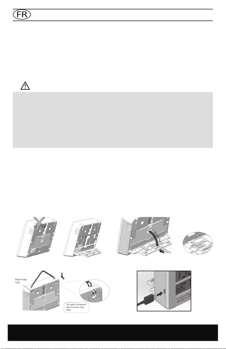
DÉPLOYEZ LE SUPPORT
BRANCHEZ LE CÂBLE D’ALIMENTATION USB
OU ACCROCHEZ LE DISPOSITIF AU MUR

9
MODE D’EMPLOI
1. Graphique CO2
1a. Coecient mulplicateur de 10 pour la
lecture des ppm
2. Lecture maximale du graphique
3. Indique la grandeur représentée du
graphique : CO2, TEMPÉRATURE ou HR
4. Cycle automaque entre CO2, HR, et
température sur le graphique
5. Lecture minimale du graphique
6. Mode végétal ou humain
7. Alarme sonore acvée/désacvée
8. Menu principal
9. Lecture de la température
10. Lecture de HR
11. Lecture de CO2
12. Temps par division (indique le temps du
graphique pour chaque division d’unité)
13. Cycle automaque entre les échelles de
temps
14. Échelle de temps (indique la période de
temps du graphique)
15. Indicateur de la zone ciblée
LECTURES DE CO2, TEMPÉRATURE ET HR
Le disposif possède trois paramètres intégrés mesurables : le dioxyde de carbone ambiant (11), la
température (9) et l’humidité relave HR (10). Ils sont en permanence achés à l’écran.
3 façons praques de mere sous tension
Installaon superposée de la baerie externe
(Baerie non fournie)
VUE ARRIÈRE
Orifice pour les vis Sangle de batterie Orifice de la
dragonne
Avertisseur
Orifice d’étalonnage
(uniquement en usine)
Support (replié)
Port USB
Capteur de
température/
HR (humidité
relative)
www.Hydrofarm.com
10
MODE D’EMPLOI
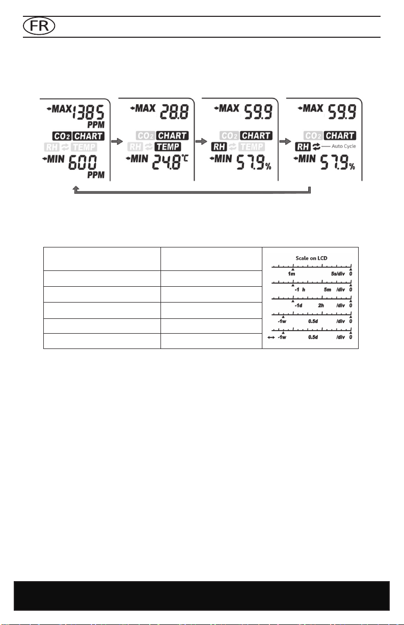
GRAPHIQUE DE TENDANCES
Le graphique de tendances (1) ache les lectures antérieures de n’importe quel de ces trois
paramètres (CO2/Temp/HR). 4 modes peuvent être séleconnés en ulisant la touche UP : CO2, TEMP,
RH et Cycle (cycles automaques CO2/Temp/HR), illustrés ci-dessous.
ÉCHELLE DE GRAPHIQUE DE TENDANCES
Un tableau indique ci-dessous les échelles disponibles de tous les paramètres (CO2, température et
HR), ainsi que la durée de chaque division pour les échelles correspondantes :
La touche DOWN permet de séleconner les échelles disponibles de chaque paramètre. Outre celles-
ci, notez qu’il existe une opon permeant un cycle automaque entre les échelles. Celle-ci peut être
acvée en appuyant sur DOWN jusqu’à ce que l’icône (14) apparaisse en bas à gauche du graphique.
MAX/MIN
Deux indicateurs numériques sont présents dans le coin supérieur droit de l’écran : Max (2) et Min
(5). Si l’échelle est modiée, les valeurs Max et Min prendront en compte les valeurs maximales
et minimales du paramètre séleconné sur le graphique (CO2, température et HR). L’unité ache
automaquement les valeurs de CO2 au démarrage.
Échelle
(Période de temps) (15) Temps par division (13)
1 m (minute) 5 secs/div
1 h (heure) 5 m/div
1 d (jour) 2 h/div
1 w (semaine) 0,5 d/div
Échelle de cycle automaque Cycle
Autres manuels pour Autopilot APCEM2
1
Table des matières
Langues :
Autres manuels Hydrofarm Moniteur


