HTS VRS N50 Manuel utilisateur

1
VRS N50 Imaging Unit
3Megapixel Network Bullet Camera Series
Quick Installation Guide

N50 Imaging Unit Series│Quick Installation Guide
2
Table of Content
WARNING ........................................................................................................................................................3
FCC Compliance Statement .....................................................................................................................4
CE Statement ................................................................................................................................................4
1. Product Overview....................................................................................................................................5
1.1 Physical Characteristics...................................................................................................................... 5
2. Preparation for Installation .................................................................................................................7
2.1 Unpack Everything.............................................................................................................................. 7
2.2 Tools for Installation ............................................................................................................................ 7
2.3 Checking Appearance......................................................................................................................... 7
3. Installation.............................................................................................................................................8
3.1 Mounting the camera onto the ceiling/wall.......................................................................................... 8
3.2 Mount the unit onto a pole ....................................................................................................... 9
3.3 Connecting the Wires ............................................................................................................ 10
3.4 Adjusting the Camera Position ...............................................................................................11
3.5 Adjusting the zoom & focus (vari-focal) / default & reset button ............................................11
3.6 Adjusting the Sun shield hood ............................................................................................... 12
3.7 Network Topology .................................................................................................................. 12
3.8 System Requirements ........................................................................................................... 13
4. IP Configuration .................................................................................................................................14
4.1 Default IP address ................................................................................................................. 14
4.2 Operating the "IP configurator" utility from your LC (Lane Controller) .................................. 14
4.3 Installing the "IP configurator" utility from HTS web site ....................................................... 14
4.4 Installing new IP address....................................................................................................... 14

N50 Imaging Unit Series│Quick Installation Guide
3
NOTICE
Please read this guide thoroughly and save it for 1future use before attempting to connect or operate this unit.
WARNING
This unit operates at AC 24V/ PoE.
Installation and service should be performed only by qualified and experienced technicians and comply
with all local codes and rules to maintain your warranty.
To reduce the risk of fire or electric shock, do not expose the product to rain or moisture.
Wipe the camera with a dry soft cloth. For tough stains, slightly apply with diluted neutral detergent and
wipe with a dry soft cloth.
Do not apply benzene or thinner to the camera, which may cause the surface of the unit to be melted or
lens to be fogged.
Avoid aligning the lens to very bright objects (example, light fixtures) for long periods of time.
Avoid operating or storing the unit in the following locations:
Extremely humid, dusty, or hot/cold environments (recommended operating temperature: -20°C to
+50°C)
Close to sources of powerful radio or TV transmitters
Close to fluorescent lamps or objects with reflections
Under unstable or flickering light sources
For eyes safety- Avoid looking directly to the LED`s illumination
WEEE (Waste Electrical and Electronic Equipment). Correct disposal of this product
(applicable in the European Union and other European countries with separate collection
systems). This product should be disposed of, at the end of its useful life, as per applicable
local laws, regulations, and procedures.

N50 Imaging Unit Series│Quick Installation Guide
4
FCC Compliance Statement
Information to the user: This unit has been tested and found to comply with the limits for a Class B digital
device pursuant to Part 15B of the FCC Rules. Operation is subject to the following two conditions: (1) this
device may not cause harmful interference, and (2) this device must accept any interference received,
including interference that may cause undesired operation. These limits are designed to provide reasonable
protection against harmful interference in a residential installation. This unit generates, uses, and can radiate
radio frequency energy and, if not installed and used in accordance with the manual, may cause harmful
interference to radio communications. However, there is no guarantee that interference will not occur in a
particular installation.
If this unit does cause harmful interference to radio or television reception, which can be determined by turning
the unit off and on, the user is encouraged to try to correct the interference. For example, try reorienting or
relocating the receiving antenna, increasing the separation between the unit and receiver, or connecting the
unit to an outlet on a different circuit.
Caution
Changes or modifications not expressly approved by the party responsible for compliance
could void the user’s authority to operate the unit.
CE Statement
Operation is subject to the following two conditions: (1) this device may not cause harmful interference, and (2)
this device must accept any interference received, including interference that may cause undesired operation.
The manufacturer declares that the unit supplied with this guide is compliant with the essential protection
requirements of EMC directive and General Product Safety Directive (GPSD) conforming to requirements of
standards EN55022 for emission, EN 55024 for immunity.

N50 Imaging Unit Series│Quick Installation Guide
5
1. Product Overview
1.1 Physical Characteristics
FIGURE 1-1: PHYSICAL DIMENSION & PICTORIAL INDEX*
*Refer to table 1-1 for definitions
Unit: ㎜
1
2
3
4
5
6
7

N50 Imaging Unit Series│Quick Installation Guide
6
TABLE 1-1: PICTORIAL INDEX DEFINITION
Index #
Name
Description
1
I/O Connector
To connect Input/ Output devices
2
Power Connector
Connects to the external power source at AC 24V only
3
RJ-45 Ethernet Connector/ PoE
To insert the RJ-45 cable for network connection as well
as PoE (Power over Ethernet)
4
Mount bracket
To connects the Mount.
5
Sun shield
To minimize the effects of rain and sunlight on image
quality.
6
Externally adjustable focal length
& focus
To adjust the Near/Far and Tele/Wide controls
7
Reset button and Default button
1. Default: To Reset all settings of the unit to factory
default by pressing for 5 seconds
2. Reset: system restart
3. Video out
TABLE 1-2: I/O CONNECTOR DEFINITIONS 1/2
Purple (Signal)
Audio in
Green (GND)
Yellow (Signal)
Audio out
Orange (GND)
Blue (Signal)
I/O out (Gate Control)
Brown (COM)
Red (Signal)
I/O in (loop Trigger)
Black (GND)
TABLE 1-3: PIN DEFINITIONS 2/2
Default
Return to factory default by press button
for 5 seconds
Reset
System restart
Video Out
To output video signal
Caution
When rotated the knob to remove the default/reset cover, please tighten the screw to avoid
water leaking after adjustment.
Note
Connectors and field wiring terminals for external Class 2 circuits provided with marking
indicating minimum Class of wiring to be used. Class 2 shall be marked adjacent to the field
wiring terminals.
Au/O AO
Au/I AI

N50 Imaging Unit Series│Quick Installation Guide
7
2. Preparation for Installation
2.1 Unpack Everything
Check everything in the packing box matches to the order form and the packing slip. In addition to this guide,
items below are included in the packing box.
One Network Bullet Camera N50 Imaging Unit
One 2-pin terminal block for power input
One printed quick installation guide
One monitor out cable
One mounting template
Six screw anchors
Six screws
One pole mount adapter
One 2" bracket
Two M4 Screws
Two M4 spring washers
Two Nuts
Please contact your dealer if any item missing.
2.2 Tools for Installation
Following tools might help you complete the installation:
a drill
screwdrivers
wire cutters
2.3 Checking Appearance
When first unboxing, please check whether if there is any visible damage to appearance of the unit and its
accessories. The protective materials used for the packaging should be able to protect the unit from most of
accidents during transportation.
Please remove the protective part of the unit when every item is checked in accordance with the list in 2.1
Unpacking Everything.

N50 Imaging Unit Series│Quick Installation Guide
8
3. Installation
3.1 Mounting the camera onto the ceiling/wall
Affix the mounting template to the desired location, knock in 6 plastic anchors after hole drilling and then lock
in 6 self-tapping screws to fasten the camera.
FIGURE 3-1: MOUNTING THE CAMERA
Fasten the securely wire according to the following figure:
FIGURE 3-2: MOUNTING THE SAFETY WIRE
Safety wire (fall prevention wire, not supplied)
N50 Imaging Unit Series│Quick Installation Guide
9
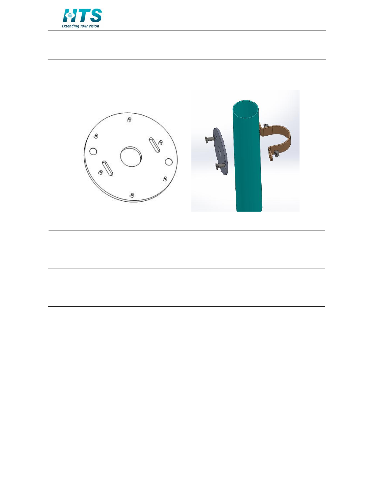
3.2 Mount the unit onto a pole
Fasten two M4 screws into the pole mount adaptor.
On the other side of the 2" bracket, screw two spring washers and two Nuts.
FIGURE 3-3: MOUNTING THE CAMERA ON A POLE
Warning
Depending on the material of mounting surface, different screws and anchors than those
supplied may be required. To prevent the unit from falling off, ensure that it is mounted to a
firm place (ceiling slab or channel) using a safety wire strong enough to withstand the total
weight of the unit. (Pay also attention to the finishing at the end of the wire.)
Caution
Safety wire must be connected with one end the wall/ceiling and the other to the safety-cord
screw of the unit. By cabling so, it is possible to prevent the unit from accidental falling in a
sudden at any time.

N50 Imaging Unit Series│Quick Installation Guide
10
3.3 Connecting the Wires
1. To attach the camera to the fixed place.
FIGURE 3-4: CONNECTING THE WIRES
2. Pass all the signal cables through the mounting bracket as the sample photo shown.
3. Connect the power cable to the power plugs with one of the following options.
AC 24V: Connect 24V (~) cables to terminals ~AC 24V
PoE: Connect the RJ-45 jack to a PoE compatible network device that supplied power through the
Ethernet cable
4. Insert audio cable and I/O cable to the unit, and connect the network cable to the RJ-45 terminal of a
switch.
FIGURE 3-5: CONNECTING THE WIRES
Table des matières
Autres manuels HTS Caméra de sécurité


